Difficult Problems:
What are the common measures to suppress zero drift?
Zero drift is a common issue in amplifier circuits, especially in DC amplifiers. It occurs when the output voltage deviates from its original zero point due to changes in temperature, component aging, or power supply fluctuations. Among these factors, temperature change is the most significant and challenging cause. Semiconductor components, such as transistors, are highly sensitive to temperature variations, which can lead to unstable performance and unwanted drift in the output signal.
When the ambient temperature changes, it affects the transistor parameters, causing the static operating point of the amplifying circuit to shift. Since direct coupling is often used between stages, this small shift gets amplified step by step, resulting in a noticeable drift at the output. The more stages an amplifier has, the greater the overall gain, and thus the more severe the zero drift becomes. The first stage of the amplifier is particularly critical, as any drift there will be magnified throughout the system.
To reduce zero drift, several practical methods can be applied depending on the specific design and application. These include:
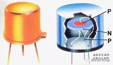
1. Using high-quality silicon transistors
Silicon transistors have significantly lower leakage currents (Icbo) compared to germanium transistors, making them more stable under varying temperatures. This is why modern DC amplifier circuits prefer silicon-based components. Additionally, the manufacturing process plays a crucial role—poorly made transistors with impurities or unclean surfaces can increase drift. Therefore, selecting well-qualified semiconductor devices is essential for minimizing zero drift.
2. Temperature compensation technique
This method uses the effect of temperature on nonlinear components to counteract the impact on transistor parameters. For example, a thermistor can be used to adjust the biasing of the circuit as temperature changes, helping to stabilize the operating point. While this approach is simple and widely used in linear ICs, it may not provide perfect compensation. A more effective version involves using two identical transistors in a differential configuration, which greatly improves the suppression of zero drift. This principle forms the basis of the differential amplifier circuit.
3. Modulation method
The modulation method works by converting the DC input signal into a higher frequency AC signal before amplification. This AC signal is then amplified using RC-coupled stages, which are less affected by low-frequency drift. After amplification, the signal is demodulated back to DC. This technique effectively separates the desired signal from the drift, allowing for better stability and reduced zero drift in the final output.
In summary, zero drift is a complex issue that requires careful design and selection of components. By employing techniques like temperature compensation, using high-quality transistors, and applying modulation, engineers can significantly improve the stability and accuracy of DC amplifier circuits.
Our Telecommunication Tower are made from quality sheet through bending, forming, automatic welding and hot galvanization. We can reach one-run machining length of 14m and can bend sheet of thickness up to 45mm. We adopt advanced welding procedures, automatically weld main joints and reach rank-II welding quality.
We have supplied 2400ton 132kV and 220kV transmission line steel pole to WAPDA. Pakistan on 2008 and have supplied 1200ton 138kV transmission line steel pole to Davao light, Philippines on 2009.
Telecommunication Tower, Telecommunication Steel Tower, Telecom Steel Tower, Telecom Steel Mono Tower
JIANGSU XINJINLEI STEEL INDUSTRY CO.,LTD , https://www.steel-pole.com