The design of chemical fiber combined air-conditioning control system
0 Preface
With the development of modern industry, the requirements for the air environment in the production process are getting higher and higher. In order to meet the needs of human comfort and technological processes, the temperature, humidity, cleanliness and flow rate of air should be adjustable in a certain space during production. In chemical fiber plants, the system that provides air conditioning for the process is called a process air conditioner. At present, the vast majority of domestic textile factories use air heat and humidity treatment with spray surface cooling. Air treatment equipment mostly uses large-scale combined air conditioners. The air conditioning system uses a double-fan air conditioning system with a constant air volume throughout the year. In this method, due to the large heat generated by the process equipment in the workshop, and the process flow has stricter temperature and humidity accuracy requirements for the air conditioning supply parameters, the air conditioning system required in the production line should be able to provide very large supply and return air volumes. And this will cause the energy consumption of the fan to be larger, accounting for about 25% of the air conditioning refrigeration energy consumption). Therefore, reducing the energy consumption of fans is of great significance to the energy-saving work of the entire chemical fiber plant.
1 Structure and working principle of chemical fiber combined air conditioner
1.1 Chemical fiber combined air-conditioning structure
The structure of the chemical fiber combined air conditioner is shown in Figure 1. This system is composed of air valve actuator, temperature and humidity sensor, differential pressure switch, differential pressure transmitter, three-way cold water valve and actuator, steam two-way valve, frequency converter and PLC. 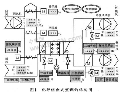
The basic task of the air-conditioning system is to keep the air in the workshop at a certain temperature and humidity, to discharge excess heat and moisture from the workshop, and to supplement it in time when the heat and moisture are insufficient. In order to accomplish this task, the temperature and humidity can be approximated to the set temperature and humidity values ​​according to the curves of isothermal humidification, adiabatic humidification, cooling humidification, etc. This paper gives the design of the air conditioning control system composed of air system, water system and steam system Program.
1.2 Working principle of chemical fiber combined air conditioner
Fresh wind windows are mainly used to introduce outdoor fresh air. To save energy, sometimes return air windows are used to introduce part of the workshop return air. The fresh air window and the return air window are generally equipped with regulating air doors to control the air intake volume and the new / return air ratio. The new / return air is usually mixed by the blower and sent to the water spray room. The spray chamber has forward spray, reverse spray and multiple rows of nozzles. The deep well water and circulating water spray small water through the nozzle, and then reversely spray the air through the circulating water to complete the adiabatic humidification process. After the deep water well water is sprayed forward, the cooling and humidification process can be completed. After the air has been treated with water, the control valve can be controlled, and the air can be humidified by isothermal humidification with steam, or the air can be heated by a humidifier with a heater. The use of water spray chamber for air treatment can make the relative humidity of the air relatively stable, which is beneficial to the adjustment and control of the relative humidity of the workshop air, thus meeting the higher requirements of the textile process for the relative humidity of the air. At the same time, the treatment of air with water can also play the role of clean air, which is conducive to reducing the dust concentration of workshop air. In addition, the use of heaters can achieve rapid temperature rise in winter.
2 System hardware design
The hardware design of this system is mainly to design the control system and the motor system. The block diagram of the hardware structure of the control system is shown in Figure 2. 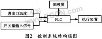
2.1 Control scheme
This design adopts DDC direct digital control, which can collect real-time display of temperature, humidity, pressure and other analog quantities and parameters of various points on site, and can also modify various set values ​​and various parameters. At the same time, it can realize automatic opening, closing and automatic adjustment of related valves and frequency converters to achieve the purpose of controlling constant temperature, constant humidity and constant pressure, and has manual and automatic switching functions.
In addition, even if the automatic control circuit fails, the system can also switch to the manual state to continue normal adjustment of various parameters.
2.2 Execution device
The actuator is the actuator that completes all actions. It can complete all the actions of chemical fiber air conditioning, including the start and stop of the fan, the start and stop of the water pump, and the control of the air valve. In the control process of the combined chemical fiber air conditioner, the controller can send a signal to the blower and the water pump. When the air valve receives the signal, it can control the air chamber. In the control process, the chemical fiber air conditioner will automatically or manually control the temperature and humidity of the workshop according to the instructions issued by the controller. The control can be performed according to the controller or the touch screen. This system is equipped with a touch screen man-machine operation interface.
2.3 Sensor
(1) Temperature sensor
This design uses the JCJ100F temperature transmitter. The JCJ100F temperature transmitter contains a high-precision linear amplifier circuit and selects high-precision components, so it has the advantages of high sensitivity, good stability, high accuracy and long service life.
In the temperature measurement and control system, a thermocouple or thermistor can be used to collect the temperature, and then the pre-amplifier circuit converts the detected tiny signal into an ADC convertible signal, and then performs A / D conversion after cold junction temperature compensation. In this way, the analog temperature signal can be digitized.
After the digital signal is handed over to the CPU for processing, the CPU can control the return air valve, exhaust air valve, new air valve, air supply valve, and inlet and return water valve according to the data of the temperature sensor, thereby completing the function of automatically adjusting the air temperature.
(2) Humidity sensor
The IH3605 humidity sensor is a capacitive integrated humidity sensor, which can be made on a ceramic substrate with a capacitive humidity sensor and a conditioning circuit. Water vapor in the air can pass through the protective polyester layer and then into the dielectric layer through the porous platinum layer to change the dielectric constant of the dielectric, thereby changing the capacitance. In this way, the capacitance / frequency and frequency / voltage conversion circuit can convert the capacitance change into a DC voltage output.
Because the output voltage of IH3605 is higher and the linearity is better, it can be directly connected to the A / D converter without amplification and nonlinear correction to complete the conversion from analog to digital. In addition, it can also be directly used as the signal source of the electronic trigger switch to start the compressor.
2.4 Controller
This chemical fiber combined air-conditioning control system uses Siemens programmable controller PLCS7-200 as the controller. S7-200 series programmable controllers can meet a variety of automation control needs. Because this design requires expansion modules, CPU222 can only have two expansion interfaces. Models above CPU222 can have 7 expansion modules. Because there are too many input points for selecting CPU226, the CPU model selected after synthesis is CPU224. At the same time, select EM222 as the expansion output module. The on-site analog input detection module selects EM231-RTD, and at the same time selects Pt100 as the temperature sensor.
The external function of the programmable controller is mainly to realize the detection and control of industrial equipment or production process through the external wiring of various interface modules. Therefore, through various input / output interface modules, the programmable controller can detect the required process information and transfer the processing results to the external process, thereby driving various actuators and realizing the control of the industrial production process. Because the signal levels in actual production are diverse, and the levels required by external actuators are also diverse, but the CPU of the programmable controller can only handle standard levels, so it should be through the I / O interface To achieve this signal level conversion. In order to adapt to various process signals, therefore, there should be corresponding multiple I / O interface modules in the design.
2.5 Design of control circuit
The whole circuit of this system is composed of three parts, namely return air system, ambient wind system and side blowing system. Depending on the current temperature and humidity, the above three parts have different operating modes. Due to limited space, the following mainly introduces the circuit part of the return air system.
The control circuit of the return air system in this system is shown in Figure 3. In the picture, when the circuit breaker QF1 is closed, the inverter is energized, the inverter's normally open contacts are closed, and the return fan is energized; when the circuit breaker QF04 is closed, the lighting lamp is on; when the short circuit breaker QF01 is closed, the power indicator is on and the fan is running At the same time, the indicator light of fan running is on. 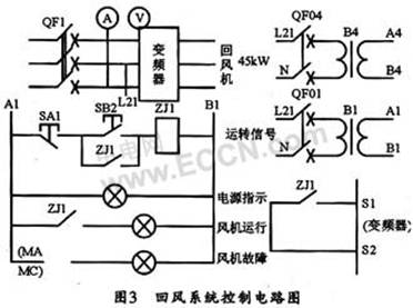
3 System software design
The software flow chart of this system is shown in Figure 4. It can be seen from the figure that when the system is running, the program should be initialized first, then enter the set parameter values ​​(wind pressure, fresh air, return air, environment, side blowing, mixed air, temperature and humidity), and then sample the workshop where it is located . After the sampling is completed, the sampled value is compared with the set parameter value, and then the new value obtained by the system after the comparison is used to automatically execute the corresponding function to complete a job. After that, the system will begin to operate in accordance with the sampling cycle . When necessary, it can also be controlled by manual control and manual intervention control. 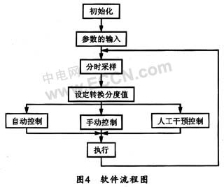
4 Conclusion
This paper gives a design method for controlling the temperature and humidity of the chemical fiber plant workshop. This method has two control methods, manual and automatic. And its electrical principle and control wiring design, neat and beautiful, friendly man-machine dialogue interface, complete functions and easy operation. In addition, after actual use, the system software runs normally and without defects. It can control the indoor temperature of the workshop at 25 ℃ ± 2 ℃, and the relative humidity is between 50% and 70%, thus fully satisfying human comfort and technological processes The need to improve the output and quality of products.
Permanent magnet stepper motors use a permanent magnet (PM) in the rotor and operate on the attraction or repulsion between the rotor PM and the stator electromagnets.
MAINTEX's PM stepper motors are widely applied in many innovative applications, including: computer equipment, photographic systems, optoelectronic devices, valve control, ATM equipment, CNC machine, automatic winding machines, electronic clocks and medical equipment, etc.
Permanent magnet stepper motor,Pm stepper motor,Permanent magnet type stepper motor
Shenzhen Maintex Intelligent Control Co., Ltd. , https://www.maintexmotor.com