0 Preface
The medical model person training system is designed to meet the needs of the majority of medical students. The development of modern medical simulation technology in China is just in its infancy. Most of the simulation system products originate from abroad. Although some products have appeared for simulating human simulation, those products are only a part of the simulating human. There is no complete system that integrates all its functions.
The medical model person training system is an intelligent model person that simulates fetal delivery and first aid for mothers and infants. It is a comprehensive teaching simulation system combined with modern science and technology. This product not only meets the teaching needs of obstetrics and gynecology, but also meets the requirements of emergency medical teaching in clinical medical education.
Obstetrics and gynecology is a clinical medicine subject with strong practicality and application. Clinical practice teaching occupies a decisive position in gynecology and obstetrics teaching. With the progress of society and the improvement of medical personnel training requirements, the traditional clinical teaching model can no longer meet the teaching needs of obstetrics and gynecology under the new situation.
In clinical medical education, first aid technology is the focus and difficulty of teaching, especially "artificial cardiopulmonary resuscitation", "cardiac defibrillation monitoring", "traumatic first aid", etc., and it is also the focus of practical skill assessment in the national licensed physician exam. Rescue of critically ill patients must be done every minute and second, and clinical first aid requires strictly trained and skilled medical personnel. However, with the improvement of the legal system, the self-protection consciousness of patients and their families has increased. It is very difficult to practice excellent first-aid techniques when rescuing patients, and it is very easy to cause medical disputes, such as emergency medical personnel. Unskilled or incorrect technology may cause medical accidents and even lead to patient death. Because clinical resources for first aid training are far from sufficient, and imported first aid models are expensive, they are rarely purchased by colleges and universities. Therefore, it is difficult for young medical personnel and medical students to master the practical skills of first aid.
1 Introduction to the medical model person training system
The medical model person training system is composed of three parts: upper computer software, lower computer hardware and model person. It can realize the case setting and complete treatment process independently. It can not only practice the training of clinical skills, but also improve the clinical thinking ability and independent treatment ability. The upper computer software design of this system adopts VC. Combining NET and openGL, the design interface is beautiful and the operation is convenient. The lower computer adopts the Lingyang 16-bit single chip SPCE061A voice chip. Due to the low price of the processor, low power consumption, and voice function, it meets the design needs of this product. The USB connection between the upper computer and the lower computer realizes high-speed and stable communication.
The content of the host computer software system includes all first-aid knowledge points from basic life support (BLS), advanced life support (ACLS) to continuous life support (PLS). The transfer system of the information collection box can be used for the operations made by the model Conduct evaluation and assessment. The software can create a variety of clinical simulated cases, which is suitable for a comprehensive system of medical training, continuing education and evaluation at different levels. The system is divided into two parts: lower computer hardware design and upper software design. The software is divided into computer software control interface and virtual monitor. The system design block diagram is shown in Figure 1.

2 Hardware system design
From the functional aspect, the hardware system is divided into four parts: model human information acquisition module, system communication module, power supply module and fetal delivery control module, as shown in Figure 2.
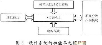
The system uses a 16-bit embedded control chip as the main controller. The processor has the characteristics of small size, high integration, easy expansion, high reliability, low power consumption, compact structure, and strong interrupt processing capability. The embedded 32 KB Flash memory FLASH, high processing speed, can easily complete the function of ordinary single chip microcomputer. The chip integrates ADC, DAC, timer / counter, RAM, FLASH and other devices, plus appropriate peripheral chips and supporting integrated development environment, can easily complete 8-channel single-channel data acquisition, adjustable sampling frequency: 1 kHz, 5 kHz, 10 kHz, 20 kHz, 50 kHz. The simulation output rate is adjustable: 4μs, 6μs, 8μs, lOμs, with output interrupt function; can communicate with PC through UART serial port. Use PDIUSBD12 chip to realize USB communication between control box and PC.
2.1 Model information collection module
The model human information collection module is divided into two parts. The first part is the position sensor information collection, and the second part is the information collection of artificial respiration and chest compressions of cardiopulmonary resuscitation.
The position sensor information collection mainly includes the collection of simulated ECG monitor information, tracheal intubation information, simulated intravenous drug administration information, simulated fetal monitor information collection, simulated blood pressure instrument information and simulated pulse oxygen saturation information collection. The main controller scans the sensor terminal in real time, picks up the sensor information, and transmits it to the upper computer through the communication system after processing. This system adopts the system expansion I / O port or the main controller I / O to connect the position sensor terminal in parallel to take the position sensor information. After the information is taken, it is transmitted to the PC through the processing of the main controller.
CPR information collection, because the model person's cardiopulmonary simulation uses airbags, so CPR information collection uses a gas pressure sensor. The cardiopulmonary resuscitation information collection uses the MPX2010 type dual-channel pressure sensor, which can provide an accurate linear voltage output directly proportional to the applied pressure. This type of sensor integrates the strain gauge and the thin-film resistance network on the same silicon chip. The correction technology realizes accurate range correction, zero deviation correction and temperature compensation. The temperature compensation range is O ~ 85 ℃, and the measurement methods are gauge pressure (G, GP) and differential pressure (D, DP). This system uses an operational amplifier to amplify the tiny voltage signal output by the pressure sensor to a level compatible with the A / D converter inside the single-chip microcomputer, so that the interface between the sensor and the single-chip microcomputer is matched. The system software calculates and calibrates the sensor's zero output and pressure range, and uploads the sensor output pressure data to the PC after processing.
2.2 Design of the communication module
The system has designed two communication methods to connect with the host computer (RS 232 serial asynchronous communication and USB communication) to meet various requirements of users.
2.2.1 RS 232 serial asynchronous communication
UART is a widely used serial data transmission protocol. The main controller of the system provides a UART communication circuit module with a full-duplex standard interface for completing serial communication between the main controller and peripheral devices. Certain conditions must be met when performing serial communication. For example, the serial port of the computer is RS232 level, and the serial port of the single-chip microcomputer is TTL level. There must be a level conversion circuit between the two. The system uses a special chip MAX3232 for conversion . The typical serial circuit design is shown in Figure 3.

2.2.2 USB communication
USB (Universal Serial Bus) universal serial bus is a new interface technology used in the PC field in recent years. It is a major PC manufacturer such as MicrosofTIntel etc. in order to solve the contradiction between the increasing PC peripherals and the limited motherboard slots and ports And a standard for serial communication.
The main advantages of USB are as follows:
(1) Easy to use. It is not necessary to open the chassis to connect peripherals, allowing peripherals to be hot swapped without turning off the power to the host.
(2) Fast speed. The maximum transmission rate of the USB interface can reach 12 Mb / s; provide a low-speed mode with a rate of 1.5 Mb / s; deducting data transmission for bus state control and error detection, the maximum theoretical speed can also reach 1.2 Mb / s and 9.6 Mb / s.
(3) Flexible connection. A USB port can theoretically connect 127 USB devices, and the connection method is also very flexible. You can use a serial connection or a hub HUB to connect multiple devices together, and then connect to the USB port of the PC.
(4) The independent power supply USB interface provides a built-in power supply.
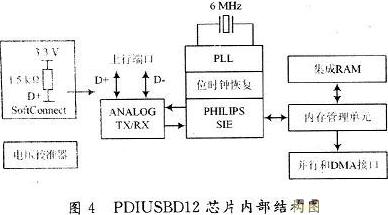
This system design uses the USB chip PDIUSBD12 to communicate with the host computer. PDIUSBD12 is a USB device with optimized performance. It is usually used in a microcontroller-based system and communicates with the microcontroller through a high-speed universal parallel interface. It also supports local DMA transmission. . The device uses a modular approach to implement a USB interface, allowing the most suitable microcontroller to be selected as the system microcontroller, allowing the use of existing architectures and minimizing firmware investment. This flexibility reduces development time, risk, and cost, and is the fastest way to develop low-cost, efficient USB peripheral device solutions. PDIUSBD12 fully complies with the USB 1.1 specification and can also be adapted to the design of most device specifications, such as imaging, mass storage, communication, printing, and manual input devices. Therefore, PDIUSBD12 is very suitable for many peripheral devices. Such as printers, scanners, external mass storage Zip drives and digital cameras. Many devices currently implemented with SCSI can directly reduce costs if implemented using USB. The low power consumption when PDIUSBDl2 is suspended and the LazyClock output meet the requirements of ACPI, OnNOW and USB power management devices. Low-power operation allows the realization of bus-powered peripherals. PDIUSBD12 also integrates features like SoftConnect, GoodLink programmable clock output, low frequency crystal oscillator and termination resistance. All these features can save costs when the system is implemented, and it is easy to implement more advanced USB functions on peripheral devices. The internal structure of PDIUSBD12 chip is shown in Figure 4.
2. 3 power module design
System power supply design is an extremely important task in this system design. It plays a vital role in the normal operation of the entire system. The power required by the system is relatively large, so this system uses a 12 V, 5 A adapter to supply power. According to the difference in power consumption and chip operating voltage, the system has designed two unrelated power groups. One way to the main controller module, the other way to the fetal delivery control module.
The power supply group for the main controller module uses a DC / DC module to step down to 5 V, and then drops to 3.3 V from the 11173.3 power chip. Among them, 5V supplies the pressure sensor and the audio system, 3.3V supplies the main controller chip, USB and the serial port chip and so on. The use of DC / DC power module has good isolation and protection, which can increase the stability of power supply.
The power supply group for the fetal delivery control module uses a 12 V adapter power supply and a 7805 step-down 5 V power supply. This module requires a large power supply, but the stability of the power supply is not very high. This design meets the requirements of the entire hardware system. The control signal is transmitted by the optical coupler in the two groups of power supplies. The advantage of the optical coupler is to completely cut off the relationship between the power supply of the two modules, making the system more stable.
2.4 Fetal delivery control module
This module is the closest embodiment of the connection between the computer and the "patient". The system has both information collection for the model person and control over the model person. This module is divided into fetal heart sound simulation, fetal birth device control and information collection, and simulation of pregnant women's contractions.
Fetal heart sound simulation adopts special audio module, and uses level trigger mode to control. The main feature of the dedicated audio module is the low power consumption of the audio module and simple control. The use of a dedicated audio chip also reduces the CPU occupancy rate of the main control chip, making the processing speed of the main control chip faster and more stable.
The fetal birth device adopts a DC motor as the driving force for the birth of a baby, and uses a groove type photocoupler and a travel switch to determine the position of the fetus. According to the design of the fetal birth device, this system adopts L298 as the motor control driving chip, and collects the position information of the fetus with I / 0 port.
The simulation of pregnant women's contractions uses a micro air pump, a gas solenoid valve and a pressure sensor. The air pump and gas solenoid valve are controlled by high-power NMOS tubes. The strength of contractions is controlled by pressure sensor feedback information.
2.5 System anti-interference and system safety design
Various forms of interference generally enter the main controller system in the form of pulses. There are three main channels for interfering into the system: space interference (field interference), channeling into the system through electromagnetic wave radiation; process channel interference, through the host The connected forward channel, backward channel and other channels connected to the host enter; the power supply system interferes and rushes through the power supply line. For the above three kinds of interference, effective measures and specific circuits must be used to eliminate them to ensure the normal operation and work of the single-chip system.
The system uses dual power supply, photoelectric isolation of the control signal, decoupling capacitor and main control chip are added between the chip power and ground, and the power supply adopts DC / DC power module to enhance the anti-interference ability of the system. In addition, the system has designed a monitoring and alarm circuit for high-power originals, which increases the stability of the system.
2. 6 CPR information data processing
The measurement of the chest compression pressure of the model person by the student is one of the main functions to be completed by the model person system. Here, the method of using a heart-lung balloon and a sensor is used to measure the chest compression pressure of the model person. When the student presses the chest balloon of the model person, the pressure in the heart and lung balloon will change, so that the output voltage waveform of the pressure sensor will also change accordingly. How to get the pressure value of the student's pressing from the output voltage of the sensor, and compare with the standard value is the first problem to be solved.
Due to the influence of many factors such as the shape of the heart-lung balloon and the sensitivity of the sensor, many disturbances inevitably appear in the collected voltage. In the actual application process, the method of combining hardware filtering and software filtering is used to eliminate noise. Hardware filtering can be achieved through a low-pass filter, and software filtering uses a median filtering method.
After a large number of experiments, it has been shown that under the same experimental conditions, the magnitude of the pressure has an effect on the output waveform of the sensor. The initial voltage V0 of the sensor is different under different pressures, and the entire compression process itself is a variable force process, so the chest compression force changes with time t, which is related to the voltage V (t) and the initial voltage V0. which is:
![]()
When the initial voltage V0 is fixed, assuming that the relationship between chest compression force and voltage is linear, the compression value can be expressed by the following formula:
 funcTIon ImgZoom (Id) // Re-set the picture size to prevent the form from being broken {var w = $ (Id) .width; var m = 650; if (w <m) {return;} else {var h = $ (Id) .height; $ (Id) .height = parseInt (h * m / w); $ (Id) .width = m;}} window.onload = funcTIon () {var Imgs = $ ("content"). getElementsByTagName ( "img"); var i = 0; for (; i
High-voltage 110~220KV XLPE Cable
A. Brief introduction of the 110~220KV XLPE high-voltage cable products
1. The cross-linkage PE insulated and wrinkled aluminum wrapper waterproof PVC Sheathed Power Cable.
Type: YJLW02/YJLLW02
Specification: 240mm²--300mm²
Voltage: 110--220KV
Usage: Suitable for damp areas and the places with a lower underground water level and to be used underground, in tunnels or pipes. Such cables bear a bigger pulling force and pressure.
2. The cross-linkage PE insulated and wrinkled aluminum wrapper waterproof PE sheathed power cable.
Type: YJLW02/YJLLW02
Specification: 240mm²--300mm²
Voltage: 110--220KV
Usage: Suitable for damp areas and the places with a lower underground water level and to be used underground, in tunnels or pipes. Such cables bear a bigger pulling force and pressure.
B. Specific property for usage of 110KV~220KV XLPE high-voltage cable
1. Cable`s conductor highest working temperature is allowed up to 90℃, and overload when meet an emergency is 130℃ ,When short circuit (in ≤5 seconds) the highest temperature is 250℃
2. When installing or laying cable, the ambient temperature should be less than -20℃, and have to give a preheat to cable.
3. The minimum bending diameter:
After laying: 30D0
During laying: 40D0
4. Allowed biggest axial traction force to outer diameter when laying cable (not consider the radial lateral
pressure at bent section) T=K×core NO. ×section (kg), in formula, the coefficient K value should be: the copper core get 7, the aluminum core get 4.
5. Allowed biggest lateral-press P, when cable is being bent
The single core cable is required P≤500kg/m.
P=T/R (T is indicated axial traction force; R is indicated radius of bent-wheel), Knowing from above formula, as the traction force is made up by length and weight of cable. So it lets P to applying requirement as above. Then the diameter of bent-wheel should be widened.
6. Cable laying is not being restricted by drop.
Of course ,except 110~220KV XLPE Cable,we have 500kv XLPE Cable,230kv XLPE Cable, 750v Cable , 132kv Cable , 110kv Cable ect.
Aluminium Corrugated Cable,Copper Wire Screened Cable,500kv XLPE Cable,230kv XLPE Cable,750v Cable,132kv Cable,110kv Cable
Huayuan Gaoke Cable Co.,Ltd. , https://www.bjhygkcable.com