1 Introduction
In the high-fidelity audio circuit, the tube amplifier has always been loved and concerned by the majority of audio lovers because of its unique charm and music listening. In recent years, high-fidelity headphones have been favored by more and more music lovers and audiophiles due to their convenience and relatively low price. In the high-fidelity earphone family, the impedance of the earphones is distributed from low resistance, medium resistance to high resistance: such as love technology's 271S rated impedance is 48Ω, Beyerdynamic's Dt48 rated impedance is 200Ω, Sennheiser HD580, HD600, HD650 The rated impedance is 300Ω. For earphones with high impedance, special matching circuits are usually needed to show their excellent performance. Compared with the speaker unit used for the sound box, the earphone has stricter requirements for its driving circuit performance index. Compared with the transistor, the static working point of the tube has a high voltage and a large internal resistance, which is more suitable for outputting a drive signal with a large swing and a small current. This feature makes the tube suitable for driving high-fidelity headphones with high quality requirements but low power requirements.
In the audio preamplifier, the ShuntRegulated Push-Pull (SRPP) circuit has the characteristics of high gain, low distortion, low output impedance, etc., and can obtain excellent sound quality performance, so it is widely used in audio circuits. This article designs a headphone amplifier circuit with a common cathode amplifier as the input stage and an SRPP amplifier circuit as the output stage. A micro-variable equivalent model is established for this circuit, a reasonable device is selected, and the corresponding parameters are controlled through theoretical calculations, so that the amplifier can better drive the headset to work.
2 Input level
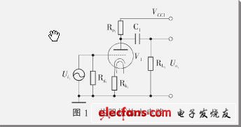
The input stage uses a common-cathode amplifier circuit composed of an electron tube triode, and its circuit schematic is shown in Figure 1. The resistors RL1, Rk1 and Rg1 in the figure are connected to the anode, cathode and grid of the electron tube respectively, so that the electron tube establishes a stable working point, and at the same time has appropriate gain and appropriate local negative feedback. V1 can choose commonly used electronic transistors, such as single transistor ECC92, or one transistor in double transistor ECC82, 12AU7, 5814 and other models. The working principle is different from the bipolar transistor in the transistor, but it is similar to the field effect transistor. Voltage-type amplifier device, its main parameters are transconductance gm, internal resistance rp and amplification factor μ, and the three meet:
The micro-variable equivalent circuit of this circuit is shown in Figure 2, where the electron tube is regarded as a controlled voltage source. In the figure, the input voltage can be expressed as:
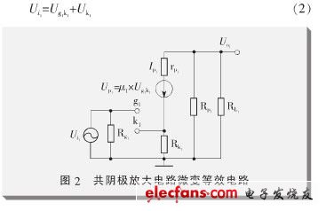
In formula (2), Ug1k1 is the voltage across the grid and cathode of the tube, and Uk1 is the voltage across the cathode resistance Rk1:
WS2811 digital led strip is single signal transmission Led, the same as WS2812B and SK6812 with three-channel circuit,
But It is difference,the WS2811 IC can be inside or outside. and the working Voltage is DC5-24V, can be program and apply to all kinds of electronic products, electrical equipment running horse lamp, led pixel screen etc.
It is the most common product and demand on the market.
Waterproof Strip,WS2811 RGB LED Strip,WS2811 LED Strip,WS2811 Digital LED Strip
SHEN ZHEN SEL LIGHTING CO.,LTD , https://www.sel-lighting.com