The loss parameters of the leaky cable system used in subways are analyzed, and it is found that the coupling loss accounts for most of the system loss of the leaky cable, and it has nothing to do with the transmission distance. When the transmission distance is long, although the signal level inside the leaky cable is still strong enough, due to the existence of coupling loss, the signal level leaking into the space has dropped below the usable value, wasting a lot of signal power. An ideal leaky cable solution should be that as the distance away from the signal feed end increases, the coupling loss of the leaky cable becomes correspondingly smaller, so that the signal level can be fully utilized to extend the coverage distance of the leaky cable. Due to the limitations of the manufacturing process, it is currently difficult to achieve this. In order to achieve a certain coverage requirement, an active repeater must be inserted to raise the level to a certain height to extend the coverage distance.
If a new radiation system is used to replace the coupling system of the leaky cable, the radiation loss of this radiation system is smaller than the coupling loss of the leaky cable, then it can cover a given one without using an active repeater It is required that the radiation system that replaces the leaky cable coupling system is a passive repeater.
Passive Repeater Site (passive repeater site), using multiple diversity reception and phase modulation technology; theoretical calculations and measured data prove: in underground (including mines, subway tunnels, etc.) communication, passive relays can be used under certain conditions The device replaces the leaky cable to cover the field strength in the weak field area.
1 Passive repeater technology
In the non-driving state, there is no problem in extending the coverage of the relay. The key is to be able to extend the coverage of the subway tunnel in the driving state. Because the tunnel is in the driving state, that is, when the traffic jams, the cross-sectional area is greatly reduced, and the transmission loss is greatly increased at this time. The passive repeater is based on the propagation characteristics of the electric wave in the tunnel and its own multiple diversity reception and phase modulation technology, making full use of The cross-sectional area during traffic jams, thereby reducing the transmission loss during traffic jams, and covering the wireless field strength of the tunnel.
1. 1 Technical Specifications WZ- 1 Passive Repeater Main Technical Specifications
â‘ Working frequency band: 150/450/800/900/1800 MHz;
â‘¡ Transmission loss of components: less than 2 dB;
â‘¢ Width factor: no more than 25 mm;
â‘£Weight: not more than 5 kg (the weight of the flat panel exciter is related to the frequency band, less than 500 g at 450 MHz);
⑤Environmental conditions: temperature: -10 ~ + 60 ℃, humidity: 90% (+ 20 ℃).
1. 2 Workflow
The passive repeater consists of shunt combiner, phase shifter, flat panel exciter and other components. According to the relationship between the transmission coefficient of the waveguide wave in the tunnel and the size of the tunnel cross section during traffic jams, passive repeaters are installed on the tunnel and the locomotive at the same time, which can effectively use the effective space of the tunnel. Thereby, the electric wave has the smallest transmission loss in the underground space, and the purpose of communicating in the tunnel is achieved. The workflow of passive repeaters is shown in Figure 1.
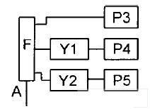
Figure 1 The working flow chart of passive repeater
When the transmitter of the communication device is working, the signal is sent to the splitter combiner F through the low-loss cable A, and the signal is divided into 3 channels by using the split function. One signal is directly input to the flat panel exciter P3; the other 2 signals pass the phase shift After inputting Y1 and Y2 into the flat panel exciters P4 and P5 respectively; at this time, the electromagnetic waves are excited by the flat panel exciters P3, P4 and P5 in the left and right and upper spaces of the tunnel, and these waves follow their own Directional reflection advances; complete field strength coverage of the tunnel space.
2 Test technology and test data
Connect the passive repeater input interface to the signal source output interface through a 2 dB attenuation cable (simulating the attenuation of the cable from the leaky cable splitter to the repeater). The signal source provides the test signal and is measured separately with a field strength meter Field strength at different locations on the avoidance line. as shown in picture 2.
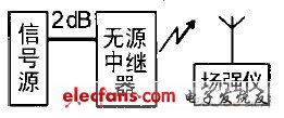
Figure 2 Schematic diagram of test technology
Signal source output power: + 10 dBm; test frequency: 818MHz and 862 MHz; modulation signal frequency: 1 kHz; signal source model: HP8648C 1; field strength meter: 1
Iron phosphate lithium ion battery cathode material for lithium iron phosphate, its safety performance and cycle life is obviously can not be compared to other materials. Iron lithium battery to solve the security problem of general battery, the general battery will produce explosion in a strong collision, hidden safety problems; While the lithium iron phosphate batteries has been rigorous safety testing, even if the internal or external battery damage, also will not burn, not explode. The cycle life of the battery is normal in general about 300 times, the highest is about more than 500 times, the use of time is generally 1 to 1.5 years; While the lithium iron phosphate batteries, the cycle life of more than 2000, the standard charge (2 hours), can reach 2000 times, using the time can reach more than 4 years, it is 2 times more than the normal battery; These power battery technology index is one of the most important.
LiFePO4 Starting Batteries
Lithium Sli Battery,Lithium Starting Batteries,Lihthium Car Battery,Lithium Car Starter Battery
Starlight Power Industrial Company Limited , https://www.starlite-power.com