Abstract: The MAX1441 is a signal-condiTIoning integrated circuit (IC) for implemenTIng capaciTIve proximity sensing in automoTIve passive keyless entry (PKE) and other applications. An interface board is needed as part of a manufacturing system to test and program end products incorporating the MAX1441. The MAXQUSBJTAG-KIT is a USB-to-JTAG interface board offered by Maxim for this purpose. This document describes the connections between this interface board and the MAX1441 application board.
IntroductionThe MAX1441 is a signal-conditioning integrated circuit (IC) for implementing capacitive proximity sensing in automotive passive keyless entry (PKE) and many other applications. The MAX1441 has two independent touch / proximity sensor channels. Comprehensive support for this IC includes: An integrated development environment, the MAX-IDE, that is an assembler, compiler, user interface, and flash programmer Example program code and typical application firmware A fully tested evaluation (EV) kit, MAX1441EVSYS, which includes the interface hardware, application circuit, and a touch-pad board with two touch pads. JTAG interface for manufacturing An interface board will be needed in a manufacturing system to test and program end products incorporating the MAX1441. Three options are available: Develop a custom interface or acquire a third party's JTAG interface board and qualify it with the MAX1441. Use the control portion of the MAX1441EVKIT by modifying the jumper setting and remo ving the MAX1441 from the EV kit board. Refer to the MAX1441EVKIT data sheet for configuring the MAX1441EVKIT board. Use the MAXQUSBJTAG-KIT, a USB-to-JTAG interface board offered by Maxim. All of these options can work equally well, once the implementation has been completed successfully. The first option, a customized board or acquiring a third party's interface board, is the most involved and potentially a time consuming choice, as it requires verification of compatibility and reliable communication with the MAX1441. The second option is the most proven because each EV kit that leaves the Maxim factory is fully tested for MAX1441 operation and interface functions. This option, however, does require altering the EV kit board and dedicating one EV kit to each test system. The third option with the MAXQUSBJTAG- KIT is quite straightforward and easy to implement, since reliable communication with the MAX1441 has been verified.
This document details the connections between the MAXQUSBJTAG-KIT JTAG interface and a typical MAX1441 application circuit. The information given here will be applicable to any board or device, including a microprocessor, which follows JTAG communications protocols.
Interface connections Figure 1 shows an application circuit with the connections between the MAX1441 and the JTAG interface on a MAXQUSBJTAG-KIT board. Please note that in this schematic, pullup resistors which are required on the JTAG lines are part of the application circuit. Typically, pullup resistors are part of the test system and there is no need for duplication on the application board.
Figure 1. JTAG interface connections between a MAX1441 application circuit and the MAXQUSBJTAG-KIT board.
Figure 2 shows the setup: the application circuit board with a test socket; a touch plate connected to the channel-2 input of the MAX1441; and the MAXQUSBJTAG-KIT board connected to a computer (not shown). Please note that the test socket included in this application board is used for engineering work and is not required by the application circuit.
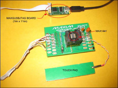
Figure 2. MAX1441 application board and MAXQUSBJTAG-KIT connection setup.
To operate the system, start with a setup similar to that in Figure 2. First, if not done already, consult the MAX1441EVSYS data sheet for installing the relevant softwares. Then use the MAX-IDE application included in the MAX1441EVSYS software package for the user interface and to program the MAX1441. Finally, consult the MAX1441 data sheet and other supporting documents, such as the MAXQ® FAMILY USER'S GUIDE or the user's guide for a specific MAXQ microcontroller, for device operation and register definitions.
IntroductionThe MAX1441 is a signal-conditioning integrated circuit (IC) for implementing capacitive proximity sensing in automotive passive keyless entry (PKE) and many other applications. The MAX1441 has two independent touch / proximity sensor channels. Comprehensive support for this IC includes: An integrated development environment, the MAX-IDE, that is an assembler, compiler, user interface, and flash programmer Example program code and typical application firmware A fully tested evaluation (EV) kit, MAX1441EVSYS, which includes the interface hardware, application circuit, and a touch-pad board with two touch pads. JTAG interface for manufacturing An interface board will be needed in a manufacturing system to test and program end products incorporating the MAX1441. Three options are available: Develop a custom interface or acquire a third party's JTAG interface board and qualify it with the MAX1441. Use the control portion of the MAX1441EVKIT by modifying the jumper setting and remo ving the MAX1441 from the EV kit board. Refer to the MAX1441EVKIT data sheet for configuring the MAX1441EVKIT board. Use the MAXQUSBJTAG-KIT, a USB-to-JTAG interface board offered by Maxim. All of these options can work equally well, once the implementation has been completed successfully. The first option, a customized board or acquiring a third party's interface board, is the most involved and potentially a time consuming choice, as it requires verification of compatibility and reliable communication with the MAX1441. The second option is the most proven because each EV kit that leaves the Maxim factory is fully tested for MAX1441 operation and interface functions. This option, however, does require altering the EV kit board and dedicating one EV kit to each test system. The third option with the MAXQUSBJTAG- KIT is quite straightforward and easy to implement, since reliable communication with the MAX1441 has been verified.
This document details the connections between the MAXQUSBJTAG-KIT JTAG interface and a typical MAX1441 application circuit. The information given here will be applicable to any board or device, including a microprocessor, which follows JTAG communications protocols.
Interface connections Figure 1 shows an application circuit with the connections between the MAX1441 and the JTAG interface on a MAXQUSBJTAG-KIT board. Please note that in this schematic, pullup resistors which are required on the JTAG lines are part of the application circuit. Typically, pullup resistors are part of the test system and there is no need for duplication on the application board.
Figure 1. JTAG interface connections between a MAX1441 application circuit and the MAXQUSBJTAG-KIT board.
Figure 2 shows the setup: the application circuit board with a test socket; a touch plate connected to the channel-2 input of the MAX1441; and the MAXQUSBJTAG-KIT board connected to a computer (not shown). Please note that the test socket included in this application board is used for engineering work and is not required by the application circuit.
Figure 2. MAX1441 application board and MAXQUSBJTAG-KIT connection setup.
To operate the system, start with a setup similar to that in Figure 2. First, if not done already, consult the MAX1441EVSYS data sheet for installing the relevant softwares. Then use the MAX-IDE application included in the MAX1441EVSYS software package for the user interface and to program the MAX1441. Finally, consult the MAX1441 data sheet and other supporting documents, such as the MAXQ® FAMILY USER'S GUIDE or the user's guide for a specific MAXQ microcontroller, for device operation and register definitions.
As users hands or debris enter the zone 6 inches (15cm) from the infrared sensor on top of the dustbin, the lid will automatically open
Rectangular Sensor Automatic Dustbin
Rectangular Sensor Automatic Dustbin
NINGBO ZIXING ELECTRONIC CO.,LTD. , https://www.zixingautobin.com