Tag: Multisim2001 electronic password lock
This article refers to the address: http://
Introduction
The common method of electronic circuit design is the experimental design method, which generally includes three stages: design proposal, scheme verification, and program modification.
Traditional experimental design methods are usually done by hand-lapped experimental circuits, often requiring repeated trials and modifications until the correct circuit is designed. With the development of electronic and computer technology, EDA (Electronic Design Automation) technology has been produced on computer platforms. In addition to powerful design functions, this technology also has functions such as testing, simulation analysis, and management. In the EAD desktop design environment, the computer is used to complete the system design and simulation of the circuit. At present, commonly used EDA technology softwares include Muhisim, .Ptotel, Pspice, Orcad, etc. Among them, Muhisim software is known as a laboratory in a computer, with good interface interaction and intuitive image. 1 Introduction to Multisim2001 Software
Muhisim2001 is a virtual EWB (electronic workbench) software developed by IIT (Interactive Image Technologies) of Canada for electronic circuit simulation. Compared with other software, this software has a huge component library, providing _r about 16 000 kinds of components and models, especially a large number of component models corresponding to real components, users can customize the properties of components, but also build their own component library, easy to call, minimize design errors, enhance the practicality of the simulation circuit It also has a humanized test function, allowing multiple test instruments (such as distortion meter, spectrum analyzer, network analyzer, etc.) to be placed on the same operation interface with the circuit diagram, and each test is performed, allowing the connection of components to go freely. According to the size of the circuit diagram, the program automatically adjusts the size of the circuit window without artificial setting.
The software provides a variety of software simulators, whether analog circuits, digital circuits, CPLD/FPGA or very complex digital devices (cPu, memory), or complex analog-to-digital hybrid circuits, can be simulated and observed result.
Multisim2001 software also provides digital instruments such as word signal generators, logic analyzers, logic converters, etc., which can solve signal generation, multi-channel waveform observation and timing comparison in digital circuits. In particular, unique virtual instruments and logic converters can realize true The mutual conversion between the value table, the logical expression and the logic circuit brings great convenience to the design of the digital circuit. The role of Muhisim200l software in digital circuits is particularly prominent.
2 The composition and principle of electronic password lock
2.1 The composition of the electronic password lock
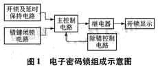
The electronic code lock is composed of a CMOS integrated circuit, and is composed of an unlocking and delay holding circuit, a wrong key blocking circuit, a main control circuit, a debugging control circuit, a relay switching circuit, and an unlocking display circuit. The password must be entered in a certain order and must be entered within the specified time. Otherwise, the lock cannot be opened even if the password is entered. In addition, the lock also has the function of blocking the wrong key and eliminating the wrong key. The block diagram of the electronic code lock is shown in Figure 1.
2.2 Working principle
The simulation schematic diagram of the electronic password lock with 4 passwords is shown in Figure 2.
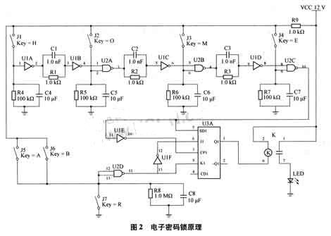
a) Main control circuit: completed by the edge triggered JK flip-flop. When JK=0l, when the rising edge of the control terminal CP occurs, Q is low level, so that the relay coil is electrically connected, triggering the switch action, turning on the circuit, and the LED (light-emitting diode) is illuminated, indicating that the password is correct and the unlocking is successful.
b) Unlocking and delay holding circuit: 4 unlocking keys are set, the tentative order is J1, J2, J3, J4, and the delay circuit uses RC circuit, that is, the charging and discharging of RC is used to achieve the purpose of delay holding. When the key is pressed, the capacitor C4 is charged to a high level, UlA outputs a low level, UlB outputs a high level, and is held waiting for the second key J2 to be pressed, if J2 is not pressed within a prescribed time, Then R1 is discharged through C1, and UlA and Ul B are restored to the original state. At this time, pressing J2 does not change the output of u2A. If the J2 button is pressed within the specified time, u2A outputs a high level and remains for a while. Similarly, press J3, J4, finally u2C output low level, generate a rising edge through ulE, trigger the main control circuit to unlock.
c) wrong key blocking and debugging control circuit: there are two wrong key blocking switches J5, J6, that is, when one or two of the two keys are pressed, the main control circuit can be locked. . The debugging key J7 is set to prevent the owner from unlocking after pressing the wrong key. When the owner accidentally presses any one or two of the J5 and J6 keys, the lock is locked and cannot be opened. Wrong key J7, then enter the password in the correct order to open this lock.
3 simulation analysis
3.1 Simulation of electronic code lock design
In the simulation electric schematic diagram, u1A, u1B, u1C, u1D, ulE, and u1F are inverters, U2A, U2B, U2E:, u2D are two-input NAND gates, and the relay switch contacts are normally open.
Entering the Muhisim200l working environment interface, it is convenient to place components and instruments: recall resistors, capacitors, relays from the Basic component box, transfer the voltage source and ground symbol from the Sources component box, and recall the NAND components from the CMOS component box. Doors, JK flip-flops, etc., call the LEDs from the Diodes component box. The circuit layout arranges the components according to the circuit schematic diagram, and places the mouse on the component pins or the instrument interface. After the mouse pointer changes to the + shape, move the mouse to the other component pin to complete the connection between the two.
The components are transferred from the component library and placed on the electronic working platform. The blue components are real components, the black components are virtual components, and the components in the circuit of Figure 2 are all real components.
The switch operation key that is called from the library is the space bar, and after double-clicking it is changed to another key. Among them, the password keys Jl, J2, J3, and J4 are H, O, M, and E keys respectively, the debugging key is R, and the wrong key is set to A, B, and the CMOs integrated circuit calls the integrated circuit with a power supply of 10 V.
3.2 Simulation process of electronic password lock
Press the simulation switch, activate the circuit, press the unlock button in turn, that is, input H, O, M, E button, the relay coil energizes and pulls, the normally open contact closes, and the LED lights up.
4 Conclusion
Design password locks with Muh:isim200l software, as if the circuit is connected on the lab panel, and is not limited by the type of components, the number of components and test equipment, with its high-quality performance, powerful analysis capabilities and online screen display The design task is completed easily, happily and effectively, which provides a new means and convenient way for electronic system design, electronic product development and electronic system engineering. The application of Multisim200l software can also improve the level of modern educational technology, improve the experimental environment, and cultivate the ability of comprehensive design and experiment.
Winnowing Machine,Winnowing Rice,Seed Winnowing Machine,Grain Winnowing Machine
Hunan Furui Mechanical and Electrical Equipment Manufacturing Co., Ltd. , https://www.thresher.nl