With the ongoing advancements in industrial automation, servo control technology, power electronics, and microelectronics have seen rapid growth. This has led to the maturation of servo motion and control technologies, making the motor motion control platform a highly effective testing method. As a result, expectations for servo performance continue to rise.
**First and Third Loop Control Principles**
1. The first loop is the current loop, which operates entirely within the servo driver. It uses Hall devices to detect the output current from each phase of the driver to the motor. Through negative feedback and PID adjustments, the current is kept as constant as possible. The current loop primarily controls motor torque, making it most efficient in torque mode where the driver's operation is minimal and its dynamic response is fastest.
2. The second loop is the speed loop. It adjusts via negative feedback using signals from the servo motor encoder. The PID output here is directly set by the current loop, meaning the speed loop includes both the current loop and speed loop control. In essence, every type of control requires a current loop to ensure accurate following. While controlling speed and position, the system essentially performs current (torque) control to achieve these objectives.
3. The third loop is the position loop, the outermost of the three. It can be constructed between the driver and the servo motor encoder or between an external controller and the motor encoder/load, depending on the specific scenario. Since the inner output of the position control loop sets the speed loop, the system runs all three loops simultaneously in position control mode. This results in the highest computational load and the slowest dynamic response.
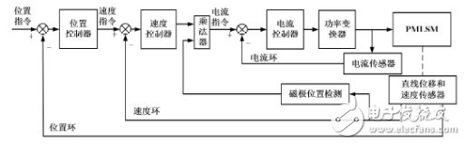
*Figure 1.1*
**Factors Affecting Control**
1. The speed loop primarily uses PI (proportional and integral) adjustments, where the ratio is the gain. Adjusting the speed gain and integral time constant helps achieve the desired effects.
2. The position loop mainly involves P (proportional) adjustments. Setting the proportional gain of the position loop suffices. When adjusting the position loop, especially in position mode, it’s best to first fine-tune the speed loop. Parameters for both loops depend on external load mechanical connections, load movement patterns, load inertia, speed requirements, acceleration demands, and the rotor and motor output inertia. A simple approach is to start with general experience values, increasing the gain parameters gradually and decreasing the integral time constant from large to small until achieving a steady state without excessive vibration or overshoot.

*Figure 1.2*
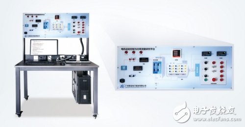
**Third, MES-100 Control Method**
1. The MES-100 motion control platform comprises a motor and loading system, a motor driver debugging system, a data acquisition and power system. From the motor to the driver, it builds a comprehensive hardware and software experimental environment, offering an open software and hardware interface. This setup provides a rich and scalable teaching experience, enabling tasks such as motor identification, stall tests, motor efficiency measurements, motor parameter tests, TN curve analysis, and more. The test results are illustrated in Figure 1.3.
2. The speed and torque control of the servo motor are managed through analog quantities, while position control is achieved via pulse signals. If there are no specific speed or position requirements, the constant torque mode can be used. Altering the analog setting changes the set torque, or the corresponding address can be modified via communication. For applications requiring precise speed and position control, speed or position modes are preferable. Position control typically determines rotational speed by the externally input pulse frequency and confirms rotation angles by counting pulses. This offers stringent control over speed and position, making it widely applicable across industries.
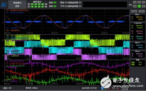
*Figure 1.3*
In summary, the MES-100 control platform is a versatile tool that supports various testing and control functions, ensuring optimal performance in diverse industrial applications.
M1 Bone Conduction Headset With MP3 And Memory Card
M1 Bone Conduction Headset With Mp3,M1 Bone Conduction Headset,Bone Conduction Headset With Mic,Bluetooth Bone Conduction Headphone
Shenzhen Lonfine Innovation Technology Co., Ltd , https://www.lonfinesmart.com