When numerous engineers use an oscilloscope to analyze the output signals of a switching power supply, they often notice mutual interference between the two measurement channels. Is this interference caused by interactions between the channels themselves? Let’s explore this further.
**I. Background Context**
When using an oscilloscope to examine the output signal of a switching power supply, it becomes apparent that there is mutual interference, or crosstalk, between the two measurement channels. Does this mean that the two channels are interfering with each other? To investigate, we conducted tests where channel 1 measured a small signal (100mV/div), while channel 2 measured a larger signal (5V/div). We then observed the mutual impact of these signals.
Methodology:
- First, we used a standard signal source to verify the factors affecting channel isolation.
- Next, we employed different measurement techniques to confirm the contributing factors of crosstalk.
**Second, Verifying Channel Isolation**
Figure 1 shows the oscilloscope's two-channel inputs directly sourced from a signal generator. It is evident that channel 2’s signal does not affect channel 1, indicating excellent channel isolation. While there are more rigorous methods to test channel isolation, this simple test suffices for our purposes.
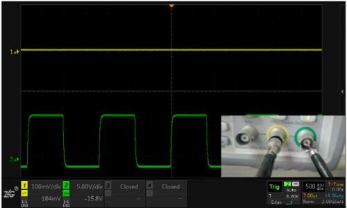
*CH1 and CH2 measure the signal generator output with proper grounding.*
**Third, Identifying the Real Cause of Interference – Grounding!**
The aforementioned interference is primarily linked to the use of the probe, particularly how the probe ground is connected. Here’s the step-by-step testing process and recorded observations:
1. Channel 1’s probe is grounded with an alligator clip, and channel 2 is left unconnected (measuring channel 1’s signal as is, see Figure 2).
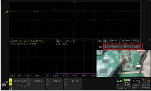
*CH1 uses an alligator clip to measure the power output, while CH2 remains unconnected. Despite the low signal amplitude of channel 1, FFT analysis reveals interference at 600kHz.*
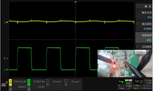
2. Both channels use alligator clips to connect to a single ground (resulting in severe crosstalk, see Figure 3).
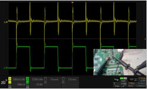
*CH1 uses an alligator clip to measure the power output, while CH2 uses an alligator clip to measure inductance, sharing a single ground point.*
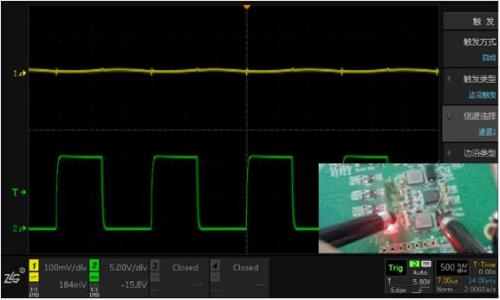
3. Channels 1 and 2 are grounded independently using alligator clips (resulting in significant crosstalk, see Figure 4).
*CH1 uses an alligator clip to measure the power output, while CH2 uses an alligator clip to measure inductance, each grounded separately.*
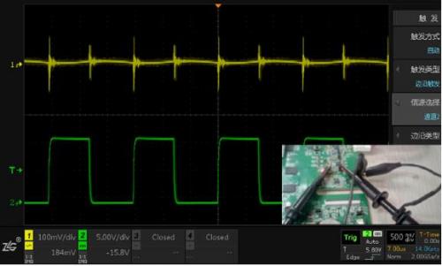
4. Channel 1 is grounded with a spring probe, and channel 2 is grounded with an alligator clip (resulting in reduced crosstalk, see Figure 5).
*CH1 uses a spring probe to measure the power output, while CH2 uses an alligator clip to measure inductance, each grounded individually.*
5. Both channels use spring probes for separate grounding (resulting in minimal crosstalk, see Figure 6).
*CH1 uses a spring probe to measure the power output, while CH2 uses a spring probe to measure inductance, each grounded individually.*
**Fourth, Summary**
- When the measuring probe and ground wire are properly connected, the inter-channel interference of the oscilloscope is negligible.
- Interference arises due to parasitic parameters of the grounding, such as lead inductance.
- When simultaneously measuring two signals, separate grounding is recommended to prevent ground loop interference.
- For sensitive signals, use a spring probe and consider using interface terminals if needed.
In conclusion, understanding the role of grounding in oscilloscope measurements is crucial for minimizing unwanted interference and ensuring accurate readings.
Fiber Optic Splicing Tray
Our Fiber Optic Splice Trays are made of ABS, light in weight and is RoHS compliant. It mainly is used for optical fiber storage and fiber optic fusion protection, easy to operate and simple to install and uninstall. The Fiber Splice Trays are stackable and can be mounted using two #6 screws; they can be used one on top of another to form a layer structure inside the fiber optic enclosures.

Usually fiber optic splice trays are used inside the Fiber Enclosures, optical fiber glass inside the fiber tray can be melt with any other strand optical fiber in the tray, thus different fiber optic cables can be melt connected directly via the tray, optical cable fiber can also be melted with the fiber optic pigtail end, and via pigtail it can connect out to other fiber optic equipment. The tray expands fiber splice capabilities as well as provides the splicing location for the fiber optic cables. we have ready stock of this series products for immediate shipment.
FO Splicing Cassette, Fiber Optic Splicing Trays, Optical Trays, Cassette for FO Splicing 12 core, Cassette for FO Splicing 24 core
NINGBO YULIANG TELECOM MUNICATIONS EQUIPMENT CO.,LTD. , https://www.yltelecom.com
