This article introduces some key procedures needed to establish a session in the 2.5G / 3G core network and service layer of packet switching. This article will first use the IMS session as a specific example, emphasizing related test challenges, and how to solve these challenges through the Tektronix G35 protocol test platform; finally, the push-to-talk based on cellular network on the 2.5G / 3G core network infrastructure ( The impact of new services such as PoC) and Multimedia Broadcast Multicast Service (MBMS) was carried out.
Introduction
The latest standardized UMTS R5 and R6 functions such as HSDPA and HSUPA are transforming mobile networks into true broadband communication systems. The continuous decline in voice revenue requires operators to seek sources of revenue growth by developing new services for customers.
The arrival of the IEEE 802.16e standard (commonly known as mobile WiMAX), an alternative mobile broadband technology, will strengthen this trend. With this new technology, competing service providers will also emerge, enabling more and more end users to adopt IP-based services in their daily lives. Welcome to reprint, this article comes from the electronic enthusiast network (http: //)
IMS and other packet data platforms enable service providers to deploy multiple services with higher QoE at a lower overall cost. A variety of applications such as ringtone downloads, text messages, emails, picture text messages, and information services are also popular. Migrating these types of services to a common platform to optimize the costs associated with operating expenses is a strong impetus for mobile (and fixed) operators to adopt IMS-based systems.
Primary / secondary PDP environment
One thing all these different applications have in common is that their availability requires specific access points. The access point is an IP router provided for the connection between the mobile station (MS) and the selected application. The MS must know the access point name (APN) in order to access the required access point through the GPRS subsystem. This is achieved through the PDP environment activation program shown in FIG. 1.
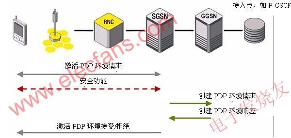
Figure 1: PDP environment activation procedure (MS enabled).
The MS sends an activation PDP environment request message containing the PDP type, PDP address, access point name, required quality of service (QoS) and protocol configuration options to the SGSN. SGSN uses APN (APN has a "fully qualified domain name" format) to select an external network reference point (GGSN). APN is a logical name that points to the external packet data network (PDN) that the user wishes to connect. The function of the domain name server is to convert the logical APN name to an IP address. According to RFC 1034, this function is a standard Internet function. In this way, the SGSN finds the GGSN connected to the required external network. Next, the SGSN initiated the "Create PDP Environment Program" to the GGSN.
The required QoS indicates the desired QoS specification. Protocol configuration options can be used to request optional PDP parameters from the GGSN. Then, the protocol configuration options are sent transparently through the SGSN.
After sending the request to activate the PDP environment, while waiting for the acceptance or rejection message to activate the PDP environment, a timer is started in the MS.
The SGSN verifies the request to activate the PDP environment. If the GGSN address cannot be obtained, or if the APN cannot be converted, or if the SGSN determines that the request to activate the PDP environment is invalid, the SGSN will reject the request to activate the PDP environment.
If the PDP environment activation procedure is successful, a user plane tunnel will be established between the MS and the external packet data network (PDP). It is important to note that this is only a user plane tunnel viewed from GPRS, and from an external PDN, it is also possible to carry control plane information such as SIP messages.
As mentioned above, the access point is the first contact point of the external service platform. Examples of these service platforms are: Short Message Service Center (SMSC); Multimedia Information Service Center (MMSC); Wireless Application Protocol (WAP); IP Multimedia Subsystem (IMS); Internet.
A GGSN can provide access to different services through different APNs. From the perspective of external PDN, it is necessary to distinguish between primary and secondary PDP environments (Figure 2). The primary PDP environment is always established for the first connection between the MS and the specific APN. If you need to establish further connections with the same APN, you can establish up to 10 secondary PDP environments. Normally, each IMS media stream will be independently routed through a separate tunnel, mainly because the GPRS charging function in Version 5 cannot generate multiple charging records for a data stream. In addition, different IMS user plane sessions may have different QoS requirements.
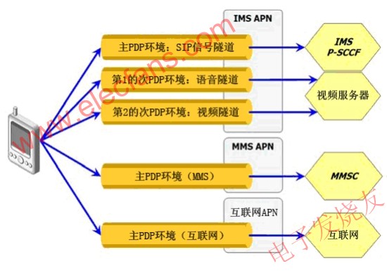
Figure 2: PDP environment type.
Therefore, the PDP environment can be divided into the following two categories. 1. Main PDP environment: Provide connections to different APNs. The SGSN assigns a unique IP address to the MS for each main PDP environment. 2. Secondary PDP environment: Provide connections for the same APN, but with different QoS. The secondary PDP environment is always associated with a primary PDP environment. The two IP addresses and access points are reused from the main PDP environment.
The QoS of any effective primary or secondary PDP environment can be changed through the MS or the network using the PDP environment change procedure. Figure 3 describes the agreed QoS parameters simulated by the G35 protocol tester.
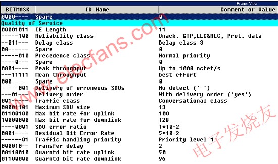
Figure 3: Quality of service IE (screen shot of G35 protocol simulator).
The maximum number of PDP environments supported depends on the capacity of the MS. A typical test mobile platform supports up to 6 PDP environments. SGSN / GGSN nodes can support up to 11 PDP environments per MS. For a complete stress test, the G35 simulates up to 6 million mobile users, and each simulated MS can have up to 11 active PDP environments. With the capacity of more than 60 million simultaneous GPRS tunnels, the G35 can simulate mobile scenarios and user loads from small to rural scale to large urban scale.
GPRS domain verification with G35
Tektronix 'G35 GPRS function and load test platform is a scalable multi-technology system. In its basic configuration, the portable device is equipped with only one analog board. For complex load scenarios, the rack system can be equipped with up to 13 analog boards. Different hardware interfaces can be combined into a cabinet, such as (GERAN) E1 board for simulating 2.5G access network, ATM board (UTRAN) for UMTS wireless access network simulation, and Ethernet board for simulating external PDN.
With its unparalleled flexibility, G35 provides simulation and simulation capabilities for a large number of network elements, so it can test GPRS subsystems under various conditions. A typical application case is shown in Figure 4.

Figure 4: Typical topology for GPRS load testing.
G35 simulates a wireless access network, including a certain number of mobile users. These users may be distributed in 60 virtual wireless cellular units, but in the simplest scenario, all simulated users are located in the same cellular unit.
Typical parameters for cellular unit setup include technology (2G, 3G), routing area code (RAC), mobile country code (MCC), and mobile network code (MNC). This method allows users to cluster users and simulate various mobile behaviors, such as: (1) moving train-all users are attached to a 3G cellular unit. After a period of time, 3G coverage is lost. All users need to perform changes between systems and attach to 2G network elements. (2) Crossing the border—Users use different RAC, MNC or MCC to switch cellular units. The routing area update procedure needs to be executed. (3) Urban area-users are almost evenly distributed in several cellular units and are switched to other cellular units in a pseudo-random manner. The user needs to perform a cellular unit reselection or cellular unit change procedure.
Using the same command will trigger all movements. According to the configuration of the unit, G35 will automatically detect and start the relevant mobility management program.
Depending on the usage, other network elements such as equipment information register (EIR), CAMEL, SMS center, positioning center, home location register (HLR), etc. can also be simulated. Many operators have a considerable number of prepaid users. Therefore, for the mixed configuration of prepaid and postpaid users, it is also necessary to simulate the relevant transaction processing of the Ge interface between SGSN and CAMEL center.
Another typical test scenario is a functional test combined with background load. This is especially important when launching new businesses. A large number of simulated users execute standard GPRS procedures, such as ATTACH, PDP environment activation / deactivation, IP conversion, and DETACH. These users constitute a group of generated background loads. Another smaller group consists of a limited number of users (such as 1 to 20), and injects new services (such as IMS) into the GPRS subsystem.
With this test method, the implementation of the protocol can be verified in all relevant aspects. For example: Does the protocol implementation meet the standards? Is it capable of withstanding abnormal behavior / unexpected error conditions? Will memory leaks occur during long-term stability testing?
Such test scenarios can also be combined with false insertion, which is a deterministic method for simulating abnormal conditions. Using this feature, test engineers can inject irregular programs into a certain amount of user traffic. There are a large number of predefined error conditions for test engineers to choose from. For example, you can reproduce a lost radio connection, simulate an unqualified cell phone (such as a repeated message), or simulate an improperly configured terminal (such as trying to connect to a nonexistent APN). For a certain percentage of users, each error will be injected in a pseudo-random manner. Different error conditions can be mixed with other conditions.
The impact of abnormal conditions and error conditions is still unclear, because these conditions often cannot be tested on real network nodes. An example of an abnormal situation is that the user initiated PDP environment activation conflicts with the network initiated DETACH procedure. The standard usually does not define the expected network line under abnormal conditions.
The combination of load testing and functional testing is a new test paradigm that eliminates the inherent drawbacks of isolated load / functional testing.
The G35 is designed to support simulation of real load and stress test scenarios. A key factor is the ability to generate control and user plane traffic. Each PDP environment can be individually associated with a specific user plane load specification. With G35, each MS can activate up to 11 PDP environments, and each PDP environment is related to another load specification.
The user plane content can be generated internally through the simulator, and it is also possible to inject external content (such as web browsing, video streams from external video servers) into the user plane tunnel.
In complex ecosystems, symptoms and their root causes are often far apart. A single miscalculated or damaged five-piece set distributed from HLR to SGSN (Gr interface) may cause an integrity check error between SGSN and RNC (IuPS interface). To completely solve the problem, the G35 combines monitoring and active test functions.
Suppose the operator wants to simulate an access network with 100,000 mobile users and wants to monitor the traffic of the core network (to network nodes such as HLR, CAMEL Camel Center), and further assume that the complete network is based on IP. Under such circumstances, the investment in test and measurement tools will be much lower than in the past, because operators only need to invest in a G35 with an Ethernet board. The Ethernet board can be used for active testing (generating load) and passive testing (monitoring) at the same time without the need for a separate protocol monitoring device.
G35 provides a large amount of statistical information and counters to support analysis tasks. Test results can be imported into an Excel file or database to support the generation of detailed reports.
Push service
Typical Internet services such as telecommunications and web browsing are generally considered pull services. End users initiate transactions and request content, such as specific web pages. The push service refers to the communication method in which the office (such as a PoC server or broadcast / multicast server) initiates transactions. Push-type transaction processing is often based on a subscription model. Users need to tell the central office in advance that “send specific information (such as sports news, weather forecasts) as soon as new content is available.
Two push services using 3GPP Release 6 have been launched. The following will carefully analyze it and study how these services affect the GPRS subsystem.
Push-to-talk based on cellular network
Push-to-talk (PoC) based on cellular networks is a new standard for providing effective and simple voice communication between user groups. The premise of this standard is that users have subscribed to one or more user groups. User equipment provides the possibility to manage PoC service settings and compile group lists. The corresponding protocols are called XCAP (XML Configuration Access Protocol) and XDM (XML File Management).
After the SIP signals are exchanged between all team members, the voice stream will be sent from the initiator to the PoC server. Then, the server distributes the voice stream to all users in the user group. Only one user at a time can have the "speaking right" and send voice data to the PoC server, which makes the service similar to "intercom". The Voice Flow Control Protocol (TBCP) is used to control the "speaking rights" assigned to PoC participants, including sending notifications that users have been granted the right to speak and their voices will be heard by other participants.
Resource efficiency is the advantage of PoC business. The user's voice information is divided and transmitted through the packet-based GPRS subsystem. Unlike typical two-way communication services, PoC only requires one unidirectional user plane channel. Although packet-oriented techniques may result in quality degradation, such as introducing a delay of about 2 seconds in the speech frame, for this type of application, the achieved speech quality is usually good enough.
Mobile broadcast / multicast service
Mobile Broadcast / Multicast Service (MBMS) is an IP data broadcast service, that is, a method of transmitting content such as video and audio clips to a large number of recipients. Therefore, MBMS is a one-to-many unidirectional bearer service, in which data is transmitted from a single source to multiple recipients. 3GPP has defined two operation modes: broadcast mode and multicast mode.
The broadcast mode is an efficient method for sending information to all users in a broadcast service area (such as a thunderstorm warning). The multicast mode is based on the subscription mode. The multimedia broadcast / multicast service has some high-level requirements: the MBMS notification procedure is used to indicate the start of MBMS data transmission; a clear mechanism is used to activate the network when there is at least one user in the cellular unit, and initiate MBMS data transmission for the multicast session in the unit ; A clear mechanism to stop the transmission of MBMS data for a given multicast session in a cell that no longer contains any active users.
The RANAP procedure between RNC and SGSN used for MBMS service activation and session start is shown in Figure 5.

Figure 5: MBMS service activation and session start.
The SGSN initiates the MBMS MS connection procedure by sending a RANAP MBMS UE connection request. Its purpose is to provide the RNC with a list of MBMS services activated by the MS. The right screenshot of Figure 5 shows the structure of this information, which was created with the G35 Message Building System (MBS). The message consists of four sequences, and each sequence contains a PLMN identification (pLMNidenTIty) and a service identification (serviceID). In this example, the RNC is notified that this particular user has started four different services. pLMNidenTIty and serviceID are represented by variables, because these parameters are also necessary to describe other information of the traffic (such as MBMS session start).
Then, the RNC confirms with the MBMS UE connection response. Since RNC does not provide an MBMS environment for this service (because this is the first time MS activates the service), it does not know the IP multicast address or APN of the service. The RNC uses the MBMS information request message to request this information from the SGSN. The SGSN responds with an MBMS information response message (parameters: IP multicast address, APN). After the business environment is created, the RNC sends an MBMS registration request message and informs the core network that the RNC is ready to receive the MBMS session start message. After the MBMS registration response, MBMS session start, and MBMS session response, the downlink data transmission is established.
How will these services affect the GPRS subsystem? Obviously, these services will cause a significant increase in user plane traffic. This causes the traffic model to become more unpredictable because the degree of uncertainty of the cellular units that are to obtain services is also increasing. Various data broadcasting services will compete for bandwidth. Therefore, the meaning of QoS is as follows: (1) Traffic reception in the broadcast area cannot be guaranteed, and the receiver may encounter data loss; (2) MBMS does not support individual relaying; (3) To reduce traffic, a network operator must only send The possibility of multicasting information to the cellular unit of the designated multicast zone containing members of the multicast group; (4) The network operator must be able to set QoS for each broadcast service individually; (5) It should be able to adapt MBMS data transmission to different RAN or currently available radio resources; (6) If there are network resource restrictions, operators should be able to define rules that support or do not support broadcast services.
Outlook
GPRS standardization was initiated by SMG (Special Action Group) of ETSI in 1994. The main GPRS specification was approved by SMG # 25 in 1997 and completed in 1999. The original GPRS conceptual design is a packet switching subsystem-the vertical expansion of the circuit-switched GSM core network.
GPRS will completely exceed the circuit-switched subsystem in the next few years. Many network equipment manufacturers strive to develop and standardize new access technologies (such as UMA and FemtoCells) in the GPRS packet switching domain, thus promoting the development of this trend.
The future mobile network architecture will be horizontal, as shown in Figure 6, which is a comprehensive network architecture based on 4G IP. SGSN and GGSN constitute the core elements of the transmission network. With the advent of LTE, these two elements will evolve into two new elements (mobile management entity) and SAE Gateway (system architecture evolution) indicated by the MME.
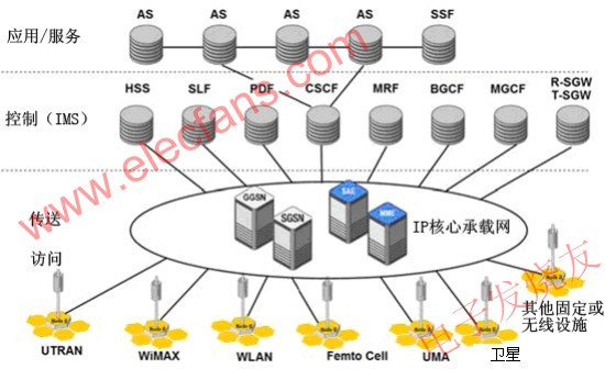
Figure 6: Integrated network based on 4G IP.
SGSN and GGSN have played a key role in ensuring the current smooth operation and seamless integration of future services into the mobile ecosystem.
The purpose of each communication system is not the technology itself, but to provide reliable support for applications and related QoE that end users believe.
For network operators and equipment manufacturers, the key is to understand how the heavily loaded GPRS subsystem works and how the GPRS network is affected by the introduction of new services and various performance requirements.
Many new services, such as PoC and MBMS, will not be deployed in early 2009. Although the first terminal will appear in 2008, it will still take several years for these businesses to become mass market businesses.
Understanding the performance characteristics of these services and other services provided under full load is the basis of the GPRS test method. As the Yankee Group (Yankee Group) pointed out, "test providers must be able to simulate the complexity and scale of the network before they can provide business with confidence." Welcome to reprint, this article comes from the electronic enthusiast network (http: //)
Tektronix G35 has the ability to complete all required tests using a single platform. Its unique characteristics, such as simulating all surrounding network elements, fault insertion, high performance, and a large number of mobile protocols, are the basis for comprehensive functional load and stress testing, not only exclusive, but also for GPRS. Tektronix's G35 and its predecessor K1297-G20 are widely used by all major network operators and network equipment manufacturers around the world. From the user's feedback, we can say responsibly that G35 is already a proven and reliable test and measurement tool.
XUNDA Electric Oven three-dimensional temperature control,make the food more delicious and more even
10 section circulation baking,
baking become so simple from now on
REMOVABLE GLASS DOOR
Triple glazing glass doors can be removed and re-attached sasilyfor cleaning.The doorframe can also be completely removed from
oven for cleaning needs.
GRADE A RATING
Three layers of glazed glass increases the safety of the oven greatly.Reflective inner glass ensures the outer door to always be safe to touch.This design. feature allows peace of-mind when operating oven.
Electric Oven
Electric Ovens,Electric Convection Oven,Electric Toaster Oven,Built In Gas Electric Oven
Xunda Science & Technology Group Co.ltd , https://www.xundatec.com