With the improvement of computer performance and the increase of communication volume, traditional local area networks have increasingly exceeded their own load. Switched Ethernet technology has emerged at the historic moment, greatly improving the performance of local area networks. Network switches can significantly increase bandwidth, and can establish relatively geographically dispersed networks. Each port of the LAN switch can transmit information in parallel, safely, and in real time, and it has stable performance, flexible structure, easy installation, and easy management. It can well meet the needs of enterprise networks and telecommunications operators' broadband access.
1 Hardware design of network switch
With the demand for security and high bandwidth in network applications, network switches are becoming more and more widely used. This switch uses the ROX bus of the AL101 chip to connect three 8-port switching chips to form a 24-port switch, which meets the user's demand for multiple switching ports.
1.1 Circuit performance requirements
The high-speed PCB circuit board of the switch has relatively high requirements on EMC and ESD. It uses high-speed clocks of 75MHz and 50MHz. The precision of the crystal oscillator is less than 50PPM. At the same time, the clock needs to be sent to different chips through the clock distribution circuit. The phase difference between the distributed clocks is less than 2ns.
The switch has 24 10 / 100M adaptive ports, and each port can achieve wire-speed switching. According to user needs, the port can be set to 10 / 100M rate, full / half duplex, flow control, static MAC address, mirroring, VLAN and so on.
1.2 Functional block diagram of the switch
The exchange technology of this exchange adopts store-and-forward mode, which is mainly composed of five parts: interface unit, exchange unit, management unit, lamp display unit and power supply interface unit. The block diagram of its composition is shown in Figure 1.
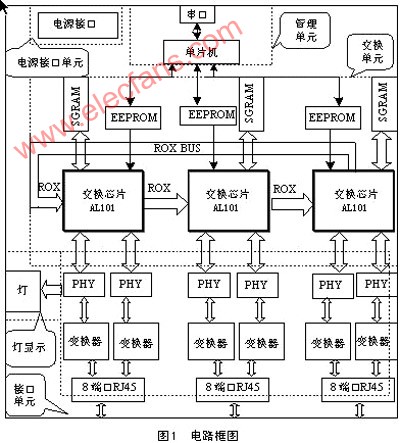 |
After receiving the data packet of the Ethernet frame structure, the RJ45 interface is sent to the PHY (physical interface chip) after transformer isolation and impedance matching, where the conversion of the analog signal to the digital signal of the RMII interface is completed and the link status is obtained , Conflicts, whether the information is too long, rate and other information.
The data enters the exchange chip (composed of three chips, forming a loop through the ROX bus, which can complete the exchange of data between the three chips), the exchange chip will obtain the destination address and source address of the data, and perform the Ethernet frame Error checking. The switching chip saves the source address in its own MAC address table, and then matches the destination address with the address in the MAC address table to obtain the corresponding port to which the data will be forwarded. If the destination port is in the same switching chip, the data is taken from the SGRAM and forwarded to the corresponding port; if the destination port is not in the same switching chip, the data is transmitted to the corresponding switching chip through the ROX bus and then forwarded out; If the corresponding destination address is not found in the MAC address table, the frame is forwarded to all ports other than the source port belonging to the same VLAN or a certain uplink port (related to the setting of the switch chip register).
The display of the light is given by the PHY, and the working speed, connection, data transmission and reception of each port can be observed through the display of the light.
The switch chip first reads the contents of the external EEPROM to initialize the switch chip register during each boot or reset. The content of the switch chip register can be read and written through the PC management program or the PC's super terminal to control or read the working configuration of the switch.
2 Software design of network switch
The software of the entire network switch system includes the control software of the single chip microcomputer, the EEPROM configuration data and the management program of the PC.
The control software of the one-chip computer mainly finishes reading and writing to the register and communicating with the PC. Through this management unit, the switch can be configured into various working modes to meet the needs of different users.
The exchange chip is connected to the EEPROM (24C02) through the I2C bus and is used to save the configuration data. When the device is turned on or reset, the device will read these data from the EEPROM for system initialization.
The management program of the PC is that the user connects the serial port of the PC to the system equipment, and the system is easily configured through the management program interface of the PC.
2.1 Software design controlled by single chip microcomputer
The management unit is composed of a single chip microcomputer and a serial port, and the EEPROM or the register of the exchange chip is configured through the PC. The single chip microcomputer mainly completes the reading and writing of registers and the communication with the PC. The serial port plays a role of connection with the PC. There is also a level conversion chip between the micro controller and the serial port to complete the microcontroller and the PC Signal conversion. Through the management unit, the switch can be configured into various working modes to meet the needs of different users, such as: 10 / 100M rate setting, full / half duplex setting, flow control, static MAC address setting, mirror setting, broadcast storm control , VLAN settings, etc. The software flow of the one-chip computer is shown as in Fig. 2.
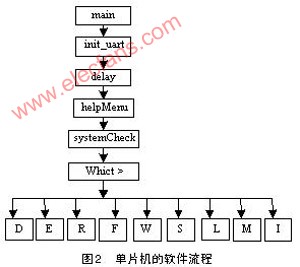 |
Each module is introduced as follows:
main-main program;
init_uart——Serial port initialization;
delay——System delay;
helpMenu——Help menu;
systemCheck——Check the system equipment ID;
whict>: —— Command prompt (whict is the abbreviation of Wuhan Institute of Chemical Technology);
D——View the entire configuration data of the system;
E——Edit the configuration data of the system;
F——Configure and manage various functions of the switch;
R——Read the configuration data of the system;
W——The system saves the current configuration data to EEPROM;
L——Configuration of system static MAC address;
M——change the password of the system;
I——System software reset;
S——The system downloads the default configuration to EEPROM.
2.2 Management program design of PC
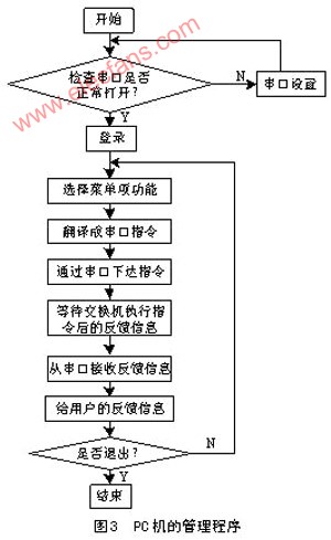
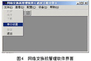
The management program of the PC is programmed in VB language and has an easy-to-understand software interface. The user can easily configure the network switch. The management program of the PC is shown in Figure 3, and the interface of the switch management software is shown in Figure 4.
 |
 |
 |
3 Performance test of network switches
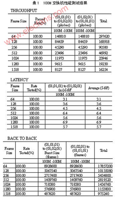
The switch was tested at room temperature (25 ° C) for 12 hours. The test instrument was Smartbits2000, which measured 4 items of transparency, delay, packet loss rate and back-to-back.
15Kw Brushless Motor,10Kw Brushless Motor,12V Brushless Dc Motor,110 Series Bldc Motor
Jinan Keya Electron Science And Technology Co., Ltd. , https://www.keyaservo.com