Application of capacitive sensor in automobile
In the past, capacitive sensors were seldom used in automotive electronics due to their characteristics of being difficult to control, difficult to read, easy to age, and strict temperature requirements. But on the other hand, they also have the characteristics of low production cost, simple shape adaptation and low power consumption, which promotes their application. Today, the emergence of a new type of measurement technology has greatly increased the number of capacitive sensors used in automobiles.
Macroscopically speaking, capacitive sensors are usually analyzed by converting capacitance into another physical variable such as voltage, time or frequency. On the microscopic level, capacitive sensors have been used in automobiles for a long time; micromechanical acceleration sensors are designed based on this principle. These are often used to detect charge transfer.
A new method for detecting capacitance uses the input stage of the improved sigma-delta converter to detect the unknown capacitance and convert it into a digital signal. This method uses a capacitance-to-digital converter (CDC). In this article, we will explain several capacitive sensor principles that can be used in automobiles. At the end of the article, another alternative method will be outlined.
Capacitance-to-digital converter
To describe CDC visually, we must introduce the principle of sigma-delta converter. Figure 1 is a simplified diagram of a sigma-delta converter.
In order to clearly understand its working process, first we look at the input of the integrator. After a long interval, this value must be kept at zero. The small step signal in a short time will be transformed into a ramp signal. By raising the output of the reference branch to the same value as the input branch, a zero average is reached, which in turn is affected by the output of the comparator. This transforms the reference point into a parallel capacitance with logic 1.
The capacitor is charged and then supplied to the integrator in turn, so that the integrator gets a negative reference voltage. Therefore, the high voltage at the input leads to a large number of logic parts, which in turn frequently use the (negative) reference voltage. The density is converted into a digitized value by the following digital filter. A classic sigma-delta converter compares an unknown voltage with a known voltage, that is, two known capacitors (usually equal) are used for this comparison.
In fact, the charge is compared, so the capacitor can be compared using the formula Q = C * V, if both voltages are known (here the same voltage value is taken). The synchronous voltage signal must also be provided to the input branch. Figure 2 shows the capacitance-to-digital converter.
This method brings many benefits. Because of its close relationship with the sigma-delta converter, its well-known characteristics can be improved and adopted. These characteristics include high noise suppression, high resolution at low frequencies, and cost-effective realization of high accuracy. Sigma-delta converters, with almost no exceptions, have a similar input structure, so different special structures can be suitable for special measurement tasks, such as extremely low current input, maximum accuracy, or higher cut-off frequency.
If we carefully examine View 2, we can clearly see more advantages. Parasitic capacitance does not play any role in the initial approximation. A parasitic capacitance tending to zero at node A has zero potential. Node B is not zero, but it is charged by a certain low impedance potential, so the parasitic capacitance at this node will charge to an average value without affecting the measurement result. The parasitic capacitance of nodes A to B is always in parallel with the measuring element, and there is usually an offset.
Existing capacitor-to-digital converters can provide very good performance. For example, ADI's AD7745 can achieve 24-bit resolution and 16-bit precision.
Figure 1: A simplified diagram of a sigma-delta converter
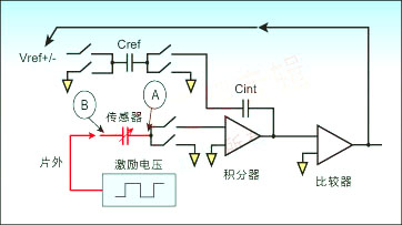
Figure 2: Capacitance-to-digital converter
Capacitive sensor
The previous capacitance analysis system requires that the measured capacitance is relatively large, and the capacitance value changes greatly when touched. For sensor manufacturers, the need for large enough changes often causes problems, but it does not appear in smaller capacitive sensors. For example, a typical 150pF humidity sensor is not only quite expensive (because it is relatively large), it is also error-prone, and its long-term stability is also poor.
The capacitance of the capacitor can be calculated according to its structure: C = εoεrA / d
Among them, εo is the vacuum dielectric constant, εr is the dielectric constant of the material, A is the area of ​​the guide plate used, and d is the distance between the two electrodes. With a few exceptions (such as pressure sensors), all capacitive sensors use changes in the surface of the guide plate or the dielectric to measure changes in capacitance. Most sensors can be divided into two categories: one is the guide plate area (geometric) changes (such as liquid level sensors or displacement sensors); the other is dependent on εr changes (such as proximity sensors or humidity sensors).
Humidity sensors are a classic example of dielectric sensors, which use a humidity-sensitive polymer layer as the dielectric. As the humidity increases, more and more water molecules accumulate, so εr increases. The sensor detects the purity of the liquid (such as oil or fuel), which is essentially composed of two fixed guide plates, and the liquid itself forms a dielectric. The necessary liquid characteristics are determined empirically (for example: increased moisture in oil or fuel). Temperature plays a decisive role and must also be determined reliably. Simple proximity sensors that measure dielectric changes usually require the most complex measurement electronics.
image 3
Figure 4
Figure 5
In many cases, the proximity sensor includes two conductors on the printed circuit board. The value of the intermediate dielectric is very small (close to 1). If an object, such as a hand, moves into the electronic area of ​​the capacitor, it changes the capacitance. The composition of the human body exceeds 90% water, so the value of the dielectric is very large (about 50).
The remote control switch is very easy to manufacture, thus making applications such as keyless ignition or clamping protection for power windows possible. An important necessary condition for keyless cars is to minimize the input current as much as possible-the standard case is less than 100A. Manufacturers have optimized sigma-delta converters for many years, so there are some suitable architectures.
The rain sensor can be implemented in a similar way. They are easy to manufacture, cost-effective, and size can also be an advantage. However, the traditional rain sensor based on the optical refraction of water droplets has only a very small active area on the windshield, which reduces the sensitivity of the system, resulting in repeated dry erase and no wipe problems.
Geometry change sensor
Examples of sensors that rely on geometric changes are pressure sensors, liquid level sensors, and displacement sensors-these sensors are simply moving the dielectric between fixed guides. The pressure sensor uses two guide plates with a fixed size as the membrane; due to the elasticity of the guide plate, the pressure on the sensor will change the distance between them.
Due to thermal diffusion, the temperature sensor needs to consider changing geometry. Imagine that one of the two electrodes is attached to the chip and the other is attached to a bracket made of metal or ceramic, so the bracket itself acts as a sensor. Taking ceramics as an example, it can withstand very high pressure and invading media. Compared with the classic Wheatstone bridge, the main advantage of capacitive pressure sensors is the lower input current requirements, making them particularly suitable for applications such as tire pressure control.
In a liquid level sensor, a pair of fixed guide plates are immersed in the liquid to be measured. Manufacturers can produce printed conductors at very low cost. The second pair of guides is attached to the bottom and can detect changes in the dielectric due to temperature or other influences, as shown in the figure below.
In all methods, the Σ-Δ technique is proved to be very satisfactory. In many cases, digital filters are necessary anyway, and they can be used to achieve the necessary dynamic characteristics. For example, a very long time constant is required in a hydraulic sensor, and the proximity sensor must adapt to the changed surrounding environment (such as the humidity sensor to adapt to rain or ice).
Alternative methods using DDS technology
This technique works in a completely different and slightly more complicated way. On the other hand, it can be used to measure complex impedance, including inductance, impedance / capacitance, or impedance / inductance sensors. In this case, the sensor is excited by a known very precise frequency. Here, direct digital frequency synthesis (DDS) technology is very suitable.
Figure 6: Using the DDS method to calculate the real and imaginary parts of the impedance
Here, the response of the sensor is recorded by a fast analog-to-digital converter and a fast Fourier analysis. With the DDS method, the initial phase can be accurately known at any time. In the same way, the response to other frequencies can also be measured. The real and imaginary parts of the impedance can be calculated accordingly and output via the digital bus. A full scan only takes a few hundred milliseconds. This figure illustrates the method.
The network analyzer circuit can be used for capacitive and inductive sensors, as well as sensors that record motion or measure the viscosity of liquids, such as engines or lubricants.
summary
Capacitive sensors are ushering in a new life in automobiles. The new method has proved its initial success in pressure, liquid level, humidity, rain and proximity sensors. Using Σ-Δ technology can provide flexible solutions to different dynamic and accuracy requirements, and make the sensor system have extremely low power requirements. CDC equipment has been used in several automotive applications, and its application in many other fields is increasing.
Xinxiang Mina Import & Export Co., Ltd. , https://www.mina-motor.cn