Research and Design of High Energy Ignition Controller for Dual-Use Fuel Vehicle
With its rich reserves, low exhaust pollution, and good economy, natural gas has gradually become a good alternative fuel for automobiles. In the conversion of dual-fuel vehicles, the original engine structure is generally not modified in order to take into account the performance when using gasoline [1]. Because the combustion characteristics of gas fuel and gasoline are different, the original ignition system cannot fully exert the efficiency of gas fuel, and the power is significantly reduced . Reference [2] designed the ignition advance angle controller for the characteristics of high octane number of gas fuel and slow flame propagation speed of gas fuel, and achieved good results. However, for different types of engines, the MAP map of the ignition advance angle is different, and the acquisition of the MAP map requires a lot of experiments. The development cycle is long and the cost is high, which limits the wide application of this type of ignition controller. The dual-fuel vehicle ignition controller designed in this paper comprehensively controls the ignition advance angle and ignition energy. There is no need to obtain the ignition MAP map, which shortens the development cycle and cost, has strong versatility, and can significantly improve the power of the vehicle and reduce emissions.
Design of ignition parameter control scheme
The performance of the ignition system is mainly reflected in the two aspects of ignition timing and ignition spark intensity [3]. Due to the slow propagation speed of gas fuel combustion, long ignition delay period, and high ignition temperature, cars need a larger ignition advance angle and ignition energy than natural gas when burning natural gas. This article controls the ignition advance angle by setting an adjustment switch on the controller to select different ignition adjustment angles according to the fuel used. The ignition angle adjustment range is from 0o to 20o. It is suitable for natural gas, liquefied petroleum gas, gasoline and other fuels. Be applicable.
For a six-cylinder engine, one cycle of the ignition signal given by the Hall sensor on the distributor corresponds to 120o of crankshaft rotation (180o for four-cylinder). If the time corresponding to the period of the ignition signal output by the measured electrical appliance is T, the crankshaft rotates 1o The time is T / 120. If the ignition needs to be advanced in advance, the phase shift in the time domain Dt = (ao / 120o) * T, where T is a measurable amount, ao is the advance angle set by the DIP switch , The adjustment range is 0-20o. When ao = 20o, Dt / T = 1/6; when ao = 10o, Dt / T = 1/12; when ao = 0o, Dt / T = 0; as long as the ratio between Dt and T is determined, You can make the ignition advance angle change to a certain value with the change of the ignition frequency. In order to make the angle adjustment more accurate, the 16 advance gears are set by the dip switch to select the advance angle, that is, the advance angle ![]() , Where x is the code value corresponding to the DIP switch,
, Where x is the code value corresponding to the DIP switch, ![]() The value of is brought into Dt = (ao / 120o) * T,
The value of is brought into Dt = (ao / 120o) * T,  , Ie 1 unit x corresponds to an ignition advance angle of about 0.67o.
The magnitude of the ignition energy is related to the magnitude of the primary current of the ignition coil. The magnitude of the primary current is controlled by the conduction time of the primary circuit, so an optimal conduction time should be controlled. The conduction time of the primary circuit of the traditional ignition system is limited by the shape of the cam or the sensor signal. Due to the unchanged duty cycle, the primary circuit has a long conduction time and a large primary current when the engine is running at low speed. The ignition coil is easily heated; at high speed , The primary circuit has a short conduction time, a small primary current, a low secondary voltage, and unreliable ignition [4]. This article uses a single-chip microcomputer to control the ignition on-time, and the setting of the duty cycle can change with the change of frequency. The charging time of the ignition coil is generally 10ms to reach saturation, so when the frequency of the ignition signal is low, the charging time is guaranteed to be 10ms; when the frequency of the ignition signal increases and the ignition cycle is less than 10ms, the discharge time of 2ms is reserved, and the rest of the time is fully turned on, fully The duty cycle of the ignition signal is used to ensure the best on-time when the engine is running at high and low speeds.
Ignition controller hardware design
The block diagram of the hardware composition of the ignition controller with single chip microcomputer as the core is shown in Figure 1.
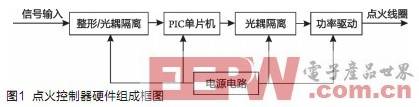
The shaping circuit shapes the signal output from the distributor to make it a pulse signal that can be processed by the single-chip microcomputer. This signal is added to the I / O port of the PIC single-chip microcomputer through the photoelectric isolation circuit. The single-chip microcomputer adopts Microchip's PIC16F73 single-chip microcomputer. This type of single-chip microcomputer has the advantages of high running speed, low power consumption, strong driving ability, and rich peripheral modules [5]. This system mainly uses the timer module, external interrupt module, and output comparison of the microcontroller Module. The single-chip microcomputer processes the input signal, and then controls the conduction and cut-off of the high-power tube in the power drive circuit through photoelectric isolation to control the ignition advance time and ignition close time. In the driving circuit, the output signal is first amplified by the triode, and then the high-power field effect tube is turned on and off, and the peak output current can reach 8-9A (the original car is 6-7A).
Since the voltage provided by the car is DC 12V, and the single-chip microcomputer needs 5V DC voltage, the corresponding power supply circuit is designed. The three-terminal voltage regulator 78M05 is used to convert 12V to 5V to power the single-chip microcomputer and other parts of the circuit.
Four dial switches are set on the controller, representing 2, 4, 8, and 16, respectively, and the ignition advance angle can be adjusted through different code combinations. The controller leads 5 lines for connecting with the car, which are 12V power line, ground line, distributor signal input line, controller signal output line, and distributor power line.
Software design of ignition controller
The frequency range of the input signal of the single chip microcomputer is 0-200Hz, the duty ratio is generally 2: 3, the falling edge of the input signal is the ignition timing, and the pulse width is the ignition coil charging time. The single-chip program completes the advancement of the ignition time and the adjustment of the duty cycle.
The flow chart of the system main program and external interrupt program is shown in Figure 2 (a) and (d). The MCU first completes the initialization of the timer, external interrupt, CCP1 and CCP2 compare interrupts, uses the external interrupt to detect the time interval between two adjacent falling edges, and stores and clears the TMR1 value in the external interrupt service program. The stored value is Period T.
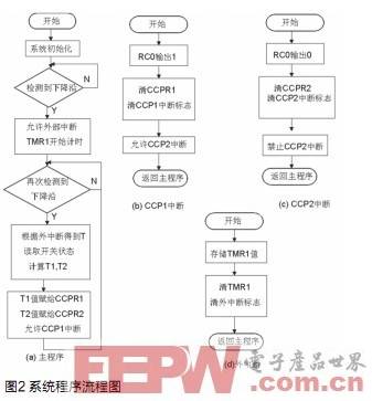
When T≥12ms, the car runs at medium and low speeds, the ignition signal can meet the charging time of 10ms and the discharge time of 2ms, and store the value of T-10ms-Dt in the CCPR1 register; when T <12ms, the ignition signal When the charging time of 12ms and the discharging time of 2ms are not satisfied, under the premise of ensuring the discharging time of 2ms, the rest of the time is all turned on, and the value of 2ms-Dt is stored in the CCPR1 register.
When T≥50ms, the car is in the starting state, and the operating conditions are unstable. In this case, the ignition advance angle maintains the original car angle; when T <50ms, the car is in normal operating conditions, and the single-chip computer detects the external switch Signal based on ![]() Calculate the ignition advance angle to determine the falling edge of the output signal (where x is the read switch value), and store the value of T2 = T-Dt in the CCPR2 register.
Calculate the ignition advance angle to determine the falling edge of the output signal (where x is the read switch value), and store the value of T2 = T-Dt in the CCPR2 register.
CCP1, CCP2 interrupt program flowchart as shown in Figure 2 (b), (c). When the value in TMR1 is equal to the value in CCPR1, the CCP1 interrupt service routine is entered, the RC0 pin outputs a high level, and the CCP2 interrupt is turned on. When the value in TMR1 is equal to the value in CCPR2, the CCP2 interrupt service routine is entered, and the RC0 pin outputs a low level. The ignition pulse signal is output through the cooperation of CCP1 and CCP2 to realize the adjustment of the ignition advance angle and the ignition duty ratio.
Analysis of simulation test results of ignition controller
The ignition controller designed in this paper is simulated on an automobile ignition test bench, and the input / output waveforms of the engine measured at different speeds and ignition advance angles using an oscilloscope are shown in Figure 3 and Figure 4.
Figure 3 shows the comparison of input and output waveforms when the input signal frequency is 50Hz and the code switch code is x = 20. It can be seen from the figure that the falling edge of the output signal is about 2.2ms earlier than the input signal, according to the formula Dt = (ao / 120o) * T is converted into an angle of 13.2o; the pulse width is 10ms, which is 3ms less than the input signal. Since the ignition coil primary circuit is turned on for 10ms, it will reach saturation, and too long time will damage the coil, so the conduction time at low speed Intercept.
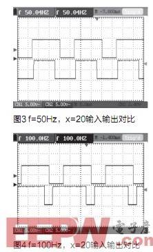
Figure 4 shows the comparison of input / output waveforms when the input signal frequency is 100 Hz and the code switch code is x = 20. It can be seen from the figure that the falling edge of the output signal is about 1.1ms earlier than the input signal, which is converted into an angle of 13.2o. The pulse width is 8ms, which is about 1.5ms longer than the input signal, increasing the conduction time of the primary current and increasing the ignition energy. .
Through waveform comparison and analysis, it can be seen that the on-time is intercepted at low speed to reduce the damage to the ignition coil; at high speed, the utilization of the duty cycle is optimized to ensure the ignition energy, and the ignition advance angle can be adjusted through the coding switch Set up to meet system design requirements.
Bench test results of ignition controller
The ignition controller designed in this paper can be significantly improved in the economic performance of multi-fuel vehicles and reduced exhaust emissions after being tested on automobile engine bench tests. The external characteristic test curve and load characteristic curve of the CA6102 gasoline engine using natural gas as the fuel are shown in Figure 5 and Figure 6.
n = 1800r / min
As can be seen from Figure 5, after the controller is installed with natural gas as the fuel for the CA6102 gasoline engine, the external characteristic power increases, increasing 1.4kW at 1800r / min, which is 2.7%, and the effective fuel consumption decreases by 4.1% on average; at 2800r / Increased 1.8kW at min to 2.8%; effective fuel consumption decreased by 3.7%; as can be seen from Figure 6, the effective fuel consumption rate on the load characteristic of 1800r / min decreased by 4.3% on average.
The test data of idling pollutants before and after installation is shown in Table 1. From Table 1, it can be seen that after the controller is installed, CO emissions are reduced by 30.5%, and CH compound emissions are reduced by 47.8%.
in conclusion
The dual-energy fuel vehicle high-energy ignition controller designed in this paper comprehensively controls the ignition advance angle and ignition energy. It only needs to be connected in series with the controller in the original vehicle distributor and ignition coil. It can work according to the fuel used. Setting the ignition advance angle through the DIP switch has the advantages of convenient use, strong versatility, and low cost. It is of great significance to the promotion of dual-fuel vehicles, energy saving, and environmental protection in China.
Wooden USB Flash Drive and adorable, people put it down
1) can be designed according to customer requirements, production of various styles, various grades of wooden U disk enclosure.
2)
can be used according to the requirements of customers maple,
Paulownia, rubber wood, rosewood and other timber for making wooden USB Flash Drive enclosure. 3)
according to customer requirements using the traditional bite tenon
technique, bonding and other techniques for making wooden USB Flash drive
enclosure.
4),
according to the requirements of customers in the wooden usb flash drive
high-grade matte coating on the shell, semi-matte, crystal, food grade
non-toxic green paint and water paint.
5),
according to the requirements of customers on a wooden usb flash drive shell
screen printing, laser engraving a variety of text, graphics, company
logo and so on.
Wooden And Bamboo Usb Flash Drive
Wooden USB Flash Drive,Bamboo USB Flash Drive,Wooden USB Stick,Bamboo USB Stick
Custom Usb Gift company limited , https://www.customusbgift.com