Principle and scheme of digital tuned filter
0 Introduction The digital or analog signal information that needs to be transmitted is generally a low-frequency signal, which must be modulated by a carrier wave to a specific radio frequency section before being transmitted through the antenna. With the development of communication technology, fixed carrier frequency technology has gradually exposed problems in security, anti-jamming and frequency band utilization in military communications. To solve these problems, frequency hopping spread spectrum (FH-SS) communication technology has gradually developed stand up. Digitally tuned filters are a type of digitally tuned control band filters that have developed with the emergence of computer control technology in frequency hopping systems and have a certain power capacity.
1 Development status of digital tuning filter technology The information transmitted by the traditional fixed carrier frequency signal transmitter can be in the form of an analog or digital signal. The signal is modulated to obtain a modulated wave signal with a fixed subcarrier frequency, which is then combined with a frequency synthesizer The output main carrier frequency signal is mixed, so that the carrier frequency of the output modulated wave signal meets the requirements of the radio frequency pass band, and then fed back to the antenna for transmission. The receiver selects the required carrier frequency signal through a band-pass filter, and after amplification, frequency synthesizer and demodulator, the information transmitted by the transmitter is obtained.
The frequency synthesizer of the frequency hopping system controls the frequency of the output carrier signal through the frequency hopping instruction. The frequency hopping command generator can continuously issue commands to control the frequency synthesizer to continuously change the frequency of its output carrier. Therefore, the modulated carrier frequency output by the mixer will also continuously jump with the instruction, so that the frequency hopping signal is sent out through the filter and the antenna. This is the frequency hopping communication technology, as shown in Figure 1.

Frequency-hopping communication is one of the most commonly used spread-spectrum methods. Its working principle refers to a communication method in which the carrier frequency of the transmitting and receiving signals is discretely changed according to a predetermined rule. Control while randomly jumping. In terms of the implementation of communication technology, "frequency hopping" is a communication method that uses code sequences to perform multi-frequency frequency shift keying, and is also a communication method that uses code-controlled carrier frequency hopping. From the point of view of time domain, the frequency hopping signal is a multi-frequency frequency shift keying signal; from the point of view of frequency domain, the frequency spectrum of the frequency hopping signal is a random hopping with unequal intervals over a wide frequency band. Among them: the frequency hopping controller is the core component, including functions such as frequency hopping pattern generation, synchronization, and adaptive control; the frequency synthesizer synthesizes the required frequency under the control of the frequency hopping controller; the data terminal includes error control of the data.
Compared with fixed-frequency communication, frequency-hopping communication is a communication method in which the sender and receiver both change the frequency synchronously, making it difficult for the adversary to track the frequency-hopping law, so it is impossible to intercept the communication content, so it has a strong ability to decipher. At the same time, frequency hopping communication also has good anti-interference ability. Even if some frequency points are interfered, normal communication can be carried out on other undisturbed frequency points. In the civil field, since the frequency-hopping communication system is an instantaneous narrow-band system, it is easily compatible with other narrow-band communication systems, that is, the frequency-hopping radio station can communicate with the conventional narrow-band radio station, which is beneficial to the updating of equipment; frequency-hopping also uses frequency division The advantages of code division multiple access multiplexing improve spectrum utilization and solve the problems of spectrum resources and channel capacity congestion.
The world's first frequency hopping radio came out in the late 1970s, and the 1980s have been a stage of continuous development and improvement of its technology. Industry insiders pointed out that frequency hopping communication is an effective means of confidentiality and combating radio interference, calling it the "killer" of radio communication. The use of frequency hopping technology in wireless communications is one of the most important methods of security and anti-interference in military communications. Compared with frequency hopping technology, cracking frequency hopping codes, fast tracking of carrier frequency and broadband high-power interference are three types of countermeasures at different levels.
Cracking the frequency hopping code is actually to crack the fast frequency hopping password and communication password, and the degree of difficulty does not need to be described; fast tracking of the carrier frequency is the main countermeasure of the current frequency hopping technology. The current technology in the United States reaches 1 000 times / s frequency sweep That is, the frequency hopping time is less than 1 ms, and the current frequency hopping technology has reached a frequency hopping time of less than 10μs. The current processing speed is also 2 orders of magnitude different from the frequency hopping technology; broadband high-power interference is a universal Interference scheme, but affected by the power of the transmitter, the power needs to reach dozens of times the transmission power of the frequency hopping radio station in order to achieve the interference effect. To combat the frequency hopping radio station, the investment is often large and the effect is small. Therefore, the current three main types of electronic countermeasures have not threatened the developing frequency hopping technology. The frequency hopping filter is a band-pass filter inserted into the channel of the transmitter and receiver system. The center frequency can significantly improve the anti-interference performance of the system, effectively improve the signal-to-noise ratio of the receiver, thereby reducing the system's requirements for frequency-hopping transceivers, making frequency-hopping communication equipment more efficient and reliable, and also achieving confidentiality. Requirements. Frequency-hopping filter technology is one of the key technologies of frequency-hopping communication. Several principles of frequency-hopping filter will be explained and compared below.
2 Frequency Hopping Filtering Technology Principles and Schemes The frequency hopping filter is to achieve a rapid change of the center frequency of the filter. The core is achieved by changing all or part of the parameters of the band-pass filter continuously or quickly. In practical applications, the frequency-hopping filter mainly has four implementation schemes: unit combined filter bank, device filter using variable parameters, digital, and digital tuned filter. The technical principles of various filters are analyzed and compared below.
2.1 Unit combined filter bank scheme The unit combined filter bank scheme is shown in Figure 2. The circuit principle is relatively easy to understand, and each band-pass filter corresponds to a center frequency. The digital tuning "control code" controls the filter array input and output "switch array" through the "controller" to switch different internal filter subunits to achieve the purpose of digital tuning and frequency selection filtering; the controller can also be adjusted manually, To achieve the purpose of tuning frequency selection filter subunit.
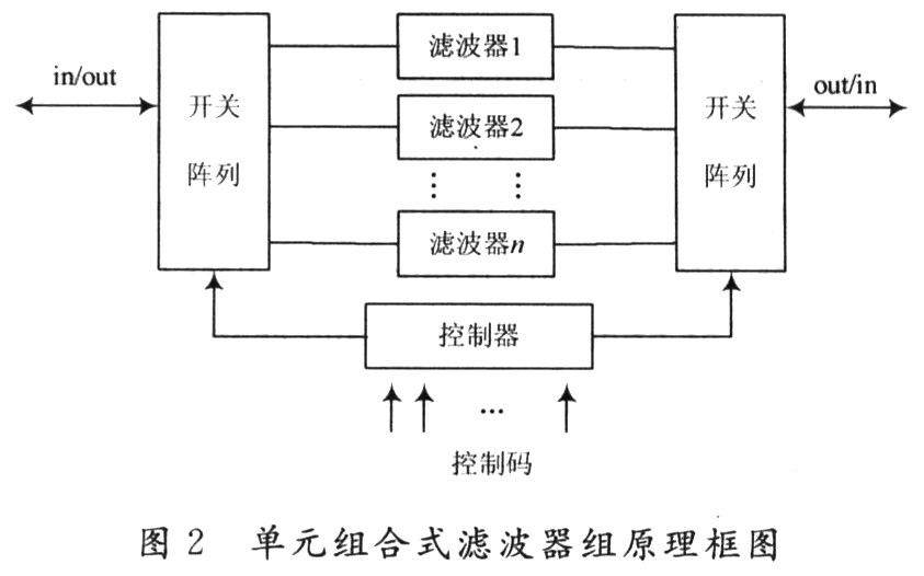
The advantages of the unit combined filter bank design structure are as follows:
Because its internal filter unit is independent, filters of various principles can be made according to requirements. The topology of filter 1 and filter 2 can be completely different, and the design and application are more flexible;
Because the switching unit only performs digital control of the switch array, the digital filter has a fast frequency hopping speed, which can reach the order of microseconds; the filtering unit is mainly composed of LC and is not affected by the static DC operating point of the semiconductor device, so the power capacity is large . At the same time, LC can choose devices with better temperature characteristics, so the temperature characteristics such as the center frequency temperature drift of the filter are better. This design structure is simple in principle and easy to implement. It has been perfected and developed in the civil field, and the early tuner and tuner tuner of the TV set is a successful example.
The shortcomings of the unit combined filter bank are also obvious:
As many frequency hopping points as the system requires, as many filter units as needed, each filter unit is independently debugged. Multi-group filter unit has many components, large volume and difficult debugging. In general, the system requirements of more than 8 groups, the large volume of multi-group filter combination is troublesome.
Multiple sets of filters are assembled in a very close space, in the RF or higher frequency bands, will inevitably cause mutual interference. That is to say, the filter is not only affected by the concentrated parameters and distributed parameters of the switch-on unit, but also by the distributed parameters of the neighboring unit. Often, one filter unit is adjusted, and the neighboring unit is abnormal. This poses high requirements on the design and debugging of the filter and the space occupied by the unit combined filter bank, which is difficult to apply in modern frequency hopping communication.
Therefore, this design structure scheme is widely used in the design of frequency hopping filters with a small number of units, but it cannot be implemented in frequency hopping communication systems with more than 250 frequency hopping points.
2. The scheme of the variable parameter device-type filter The scheme of the variable parameter device-type filter is shown in Figure 3. The key of the scheme is that there is a device with controllable parameters inside the filter. Similarly, the digital tuning "control code" controls this device through the "controller", for example, by controlling the parameters of the voltage control element and the varactor diode, the overall parameters of the filter are changed, thereby changing the center frequency of the filter to achieve digital tuning The purpose of frequency selection filtering.
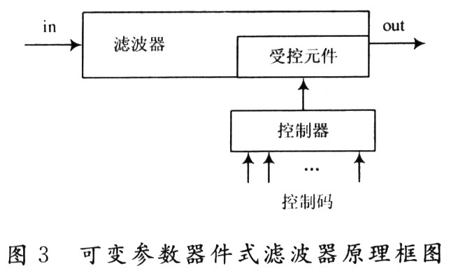
The advantage of the variable parameter device filter scheme is that the circuit volume can be made very small, and the circuit debugging is also relatively convenient. Therefore, with the combination of phase lock and digital storage technology, it has been improved and developed in the civilian field. The device is a very successful example.
The disadvantage of the variable-parameter device-type filter scheme is that the "parameter-variable" device generally has poor linearity and a small controllable range, which can be improved by the segmented tuning method; the accuracy of active control of such devices is poor, although It can be compensated by the technology of equal lock, but the frequency and speed of the phase lock are both low, which is limited by the frequency and speed of the phase lock. The variable parameter device filter is difficult to use in the field where high frequency frequency hopping is required; generally the temperature The characteristics are poor, and the electrical performance of the filter cannot be extended to the military temperature range; the power capacity of the controlled devices is small and cannot pass the power signal. It is suitable for signal processing, not suitable for use in transmitters and receivers. Therefore, variable-parameter device filters are difficult to apply in military frequency-hopping communications.
2.3 Digital filter scheme The block diagram of the digital filter is shown in Figure 4. Its scheme is based on digital signal processing. The input analog signal is first converted into a digital signal through the A / D converter, and then passed through the FFT of the microprocessor. (Fast Fourier Transform) and IFFT (Inverse Fast Fourier Transform) transforms the filter function algorithm to process the data, and finally outputs the processed signal through D / A conversion.
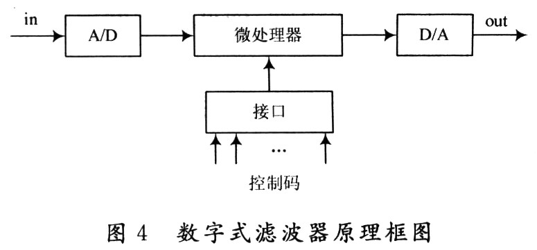
The advantages of the digital filter scheme: relying on the microprocessor can use very complex algorithms and design suitable programs. The actual functions that can be completed can go far beyond the filtering requirements, and can even realize various signal analysis and identification work. The software processing method is flexible and the processing accuracy is high. This is the advantage of this solution and the development trend of all signal processing fields in the future.
However, the disadvantage of this scheme is that: based on signal processing, the power capacity is small and cannot be transmitted through power signals; depending on the speed of the microprocessor and A / D, D / A conversion, the current processing speed is slow and can only be suitable for processing hundreds Signals below kHz; signals can only be transmitted in one direction.
In addition, digital filters also have a branch-programmable filters. MAXIM has produced the MAX264 single-chip programmable filter. The device integrates the resistors and capacitors required by the filter, no external device is required, and its center frequency, Q value and working mode can be controlled by pin programming settings. MAX264 can work in band-pass, low-pass, high-pass, band-trap, or all-pass modes, and its pass-band cut-off frequency can reach 140 kHz; it can complete a simple CNC tuning function, but its control points are very few, the maximum operating frequency The temperature characteristic is relatively low, which is far from meeting the requirements of frequency hopping radio stations currently working in the radio frequency field. The frequency gap is 3 to 4 orders of magnitude. Some people use "programmable logic devices (FPGAs)" or "application specific integrated circuits (ASICs)" to make related products. The so-called "high frequency" can only reach 1 MHz, and the requirements for military communications are also several orders of magnitude different. . Single-chip programmable filters are the direction of development. A gap of several orders of magnitude requires at least ten years of technological development to keep up.
2.4 Digital tuned filter scheme The block diagram of the digital tuned filter is shown in Figure 5. The control code controls the digital logic through the input interface circuit. The digital logic includes logic circuits such as shift register, program-controlled vibrator, etc. Data is read in, converted into a control sequence, a switch drives the array, and drives the combination of the closing and opening of the capacitor array in the filter, thereby controlling the filter parameters, that is, by controlling a smaller number of components with different weights in the filter Filter frequency selection is achieved to achieve the effect of controlling the filter's amplitude-frequency characteristics.
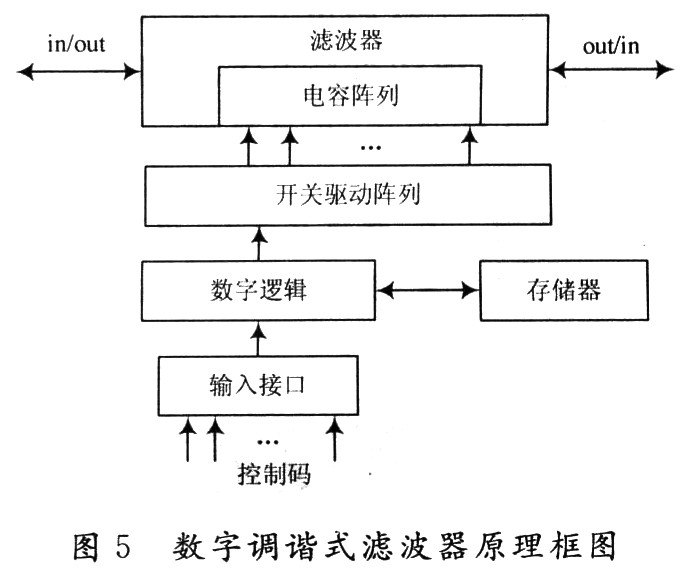
Advantages of digitally tuned filters: frequency is the result of combining the parameters of different weighted components in the filter. There may be dozens, hundreds, and thousands of combinations for each specified frequency. We can choose the best filter from them The combination of amplitude and frequency characteristics, so the frequency control characteristics of the digital tuning filter are very good.
Because the frequency is generated by combination, it overcomes the problem of non-linearity of single component parameters of other schemes, and can make the points to be evenly distributed, for example, 250 points to be selected are more evenly distributed between 1O and 30 MHz, and each step is 0 .08 MHz. And because the frequencies are generated by combination, they can be combined with a minimum number of components with different weights. Therefore, a set of hardware can combine multiple frequencies, which overcomes the shortcomings of multiple filter banks for multiple center frequencies.
This solution controls the array of capacitive elements in the LC filter, retaining the advantage of large LC filter power capacity. It is also an advantage that the signal can be transmitted in both directions. The control of this digital tuned filter is controlled by the switch control array of the frequency hopping pattern, and the speed can be very fast, meeting the requirements of military frequency hopping communication.
The disadvantages of this solution are: the circuit is complex, which is a combination of digital circuits and analog circuits; the volume is medium; the control device is added, and the loss is added; due to the structural complexity, it is difficult to make a high-order filter; The support of software has high requirements on the hardware and software of peripheral adjustment and test systems. Through the above analysis and comparison of the frequency hopping filter principle scheme, the digital tuned filter is suitable for military frequency hopping communication requirements.
3 Key technologies of digital tuned filters Digital tuned filter circuits involve hardware technologies such as digital logic circuits, high-voltage driver circuits, microwave PIN arrays, capacitor arrays, magnetic powder core transformers and other components. The design and manufacture of the filter unit group is the key technology of the digital tuning frequency hopping filter hardware.
The principle of the circuit is to use a software method to obtain a variety of weighted device parameter combinations, and then generate the filter module function. Therefore, pure hardware does not have the functions of frequency hopping and frequency selection, but also requires internal software support in the module circuit. The production process of the filter subunit group of the digital tuning frequency hopping filter will produce the uniqueness of the circuit hardware, that is, the electrical performance characteristics of each circuit are different from each other, so the internal adaptation software of each circuit The data is also different, and the copied software will not meet the module performance index. Therefore, in addition to the hardware requirements, a complex software debugging system is needed to debug and test each circuit, and to give each circuit's internal software its own unique performance software. The debugging and testing software system of digital tuning frequency hopping filter is the key technology of digital tuning frequency hopping filter software.
4 Conclusion Digitally tuned frequency hopping filter is one of the key components of military frequency hopping communication. Digitally tuned frequency hopping filter is a type of multi-point frequency hopping, high frequency accuracy, can pass a certain power, suitable for radio frequency program-controlled filters. It has the irreplaceable advantages of unit combined filter, variable parameter device filter, digital filter and so on. Each module is equipped with unique and distinctive software which is the biggest feature of digital tuning frequency hopping filter. The best software cooperates with hardware to complete the best performance of the module.
LED street lamp refers to the street lamp made with LED light source, which has the unique advantages of high efficiency, safety, energy saving, environmental protection, long life, fast response speed, high color rendering index, and is of great significance to urban lighting energy saving.
Led Road Light,Led Off Road Lights,Led Roadway Lighting,Cob Led Road Light
Yangzhou Heli Photoelectric Co., Ltd. , https://www.heli-eee.com