Low-cost assisted driving system based on ZigBee / IEEE 802.15.4
introduction
This paper presents a complete ZigBee â„¢ -based driving assistance system solution, which fully utilizes the ZigBee protocol with low cost, low power consumption, and safe wireless network features.
The program will remind and notify the driver when the driver approaches a preset road point on the highway. The ZigBee-based device is installed at each road point, and related information is broadcast to the approaching vehicle of the built-in ZigBee device. This system greatly reduces the dependence on human vision and road lighting conditions.
ZigBee Network
The ZigBee network protocol stack is built on the IEEE 802.15.4 standard that defines the physical layer (PHY) and medium access control layer (MAC) for low data rate, low power networks. ZigBee adds network (NWK) layer and application layer (APL) specifications above 802.15.4, thus forming a complete ZigBee protocol stack.
For more information about the ZigBee network, please refer to the Beyond Bits No. 4 article, based on ZigBee / IEEE 802.15.4 location monitoring.
The network of this solution has the following types of ZigBee nodes:
â— Gateway node: This node is located in a traffic control station or police station, and is used to synchronize and collect information about nearby waypoint nodes. Each gateway node will be connected to the Internet via Ethernet. Therefore, the Internet will serve as a central network connecting gateway nodes. Traffic data recording applications, or any application that falls within the scope of city management authority and requires a wide range of coverage, requires a network of waypoint nodes. This facilitates the collection and analysis of central data, as well as the updating and maintenance of remote nodes.
â— Waypoint nodes: There are two types of waypoint nodes: network nodes and independent nodes. Network nodes perform heavy data recording operations and are permanently connected to a gateway node. Such nodes can be arranged at main roads, highway entrances, and major intersections. In addition to acquiring and transmitting traffic information, these nodes can also broadcast useful driving information to vehicle-mounted nodes, such as nearby gas stations or hospitals.
These waypoint nodes should be able to handle traffic in any direction of the road. Therefore, each vehicle-mounted node needs to inform the waypoint node of its driving direction, and the waypoint node will feed back relevant information. Because these nodes and gateway nodes form a network, they can get the latest landmark and utility information in their neighboring areas.
â— The independent node is used for temporary deployment, and it is not necessarily connected to the gateway node in the area. They can be used as emergency notices to warn of traffic accidents ahead, construction in progress and other road hazards. Once the danger is resolved, these nodes will be removed. Independent nodes can also be used as advertisements, which does not require connection to the waypoint network managed by the city.
â— Vehicle-mounted nodes: These nodes are placed in each vehicle to communicate with waypoint nodes. These nodes have a personal computer interface, such as a keyboard, LED or LCD screen, etc., to facilitate users to use the system.
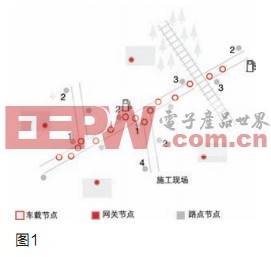
As shown in Figure 1, the waypoint nodes labeled 1–4 will effectively perform the following functions:
1. Provide traffic warnings about potential blind spots;
2. Provide various landmark information. Such as gas stations, shopping malls and hospitals;
3. Provide information about trains approaching railroad crossings;
4. Temporarily provide a warning about buildings and other traffic obstacles.
In the next chapter, we will see that all nodes work together and can support multiple applications at the same time.
Set up
Each ZigBee in-vehicle node has a unique ID assigned to it, just like the number plate of a car.
The vehicle-mounted node sends out "ping" data packets containing IDs at periodic intervals. Once the "ping" data packet is received, the waypoint node will send back a specific message data.
application
Broadly speaking, applications can be divided into the following three categories.
Road condition warning
Road condition warnings will use information to alert drivers to dangerous conditions on the road ahead. Waypoint nodes can detect approaching vehicles and transmit warning messages to explain the imminent danger, such as:
◠Speed ​​limits and traffic restrictions caused by uneven roads; turning blind spots; road maintenance; no parking, no entry or changes in speed limits, such as school districts; pedestrian crossings and entrances to hospitals or fire stations; vehicles entering one-way traffic roads, many Appears in hilly areas.
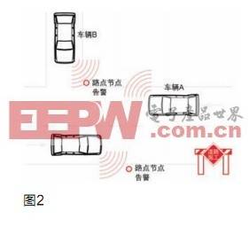
Figure 2 shows how to set up a waypoint node device to give car drivers warning in advance to take corrective measures in a timely manner. The warning process for vehicles near turning blind spots is as follows:
â— In Figure 2, the waypoint node detects that vehicle A is approaching the intersection (receiving vehicle A's ping packet).
â— The waypoint node then records the ID of vehicle A and issues a warning message of “turning blind spotâ€.
â— After receiving the warning message, the on-board node of vehicle A will send the driver both audio and video "turning blind spot" warning messages.
â— Now, vehicle A is still within the range of the waypoint node, and vehicle B has also entered the range of the waypoint node.
â— When the waypoint node detects vehicle B, it will change its broadcast message to "multiple cars approaching the turning blind spot". Because it is a broadcast message, it will be received by both vehicles.
â— The on-board nodes of the two vehicles will send out an audio alarm again and turn on a red LED. A warning message will also appear on the LCD display of each car.
â— The drivers of the two vehicles can slow down or stop as required.
â— When both vehicles leave the range of the waypoint node, the node stops broadcasting.
For all road condition warnings, the placement of waypoint nodes must ensure that warning messages can be sent to the driver as early as possible, so that they have enough time to respond. The correct placement depends on the following factors:
Factor 1: Broadcast range of waypoint node or vehicle node (whichever is shorter)
Factor 2: ZigBee data transmission rate between the vehicle node and the waypoint node
Factor 3: the average human reaction time
Factor 4: Speed ​​limit, which helps determine the average distance required to stop the car
Let us assume that vehicle A and vehicle B approach the blind turning point at 70 km / h (19.44 m / s) at the same time. This speed is the speed limit (factor 4). Factor 1 is equal to 50 meters (conservative estimate), and the data transmission rate is 50 Kbps (factor 2). At a speed of 70 km / h, the braking distance is approximately 43 meters, which includes the driver's reaction time. For example, the warning message is 800-bit data.
Then, A and B will be found at a distance of 50 meters from the waypoint node, and at a data transmission rate of 50Kbps, sending an 800-bit warning message takes only 16 milliseconds, and the driving distance is about 32 centimeters during this time. If this number is subtracted from 50 meters, there is still a braking distance of more than 43 meters.
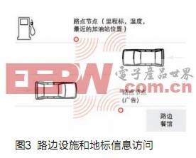
Information broadcasting
Such applications provide drivers with information ranging from unsafe emergency information to various commercial advertisements.
Some examples:
â— Road signs
â— Recently refueling / gas station
â— The nearest hospitals, hotels, markets, car service stations and landmark information
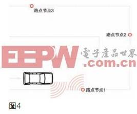
â— Direction guidance, such as destination A is 2 kilometers in front of the current location, destination B is 3 kilometers to the right of the current location and destination C is 3 kilometers to the left of the current location
â— Advertising for roadside restaurants
data record
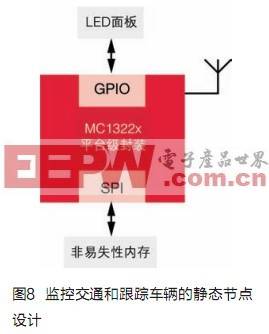
Every waypoint node at the main intersection and main highway entrance can save the ID and time information of passing vehicles. The node records the entry and exit time of the vehicle and the stay time within its range within its monitoring range. This helps city planners to grasp the overview of traffic patterns and flows.
In a specific location, dozens of waypoint nodes can be connected to a gateway node through the mesh network, which in turn is combined with an administrative office LAN. The gateway node will periodically query the waypoints in each mesh network Node to update its master log. The main log information can be used to generate a daily or monthly comprehensive report. By integrating air quality, temperature and humidity sensors into one waypoint node, local air quality can also be effectively monitored. Since these applications require large amounts of data recording, fast, long-life, non-volatile memory with error correction should be included in the waypoint node.
The solution can also track stolen or escaped vehicles through the following steps:
â— Once a vehicle has issued a warning message, each gateway node will receive the ZigBee node ID number of that vehicle.
â— Subsequently, the gateway node transfers it and a "red alert" packet to its respective waypoint node.
â— The waypoint node then enters a special mode where they compare their respective recorded vehicle ID with the "red alert" ID. When the waypoint node finds a match, it will remind the net joint.
â— A rough driving route can be recorded, including the time when each waypoint node identifies the vehicle.
System details
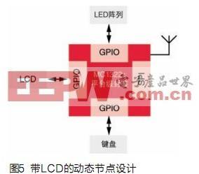
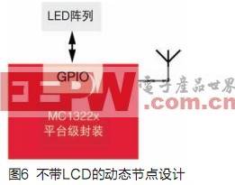
We have introduced the concepts of "dynamic unit" and "static unit" here. The ZigBee unit installed in the car is called a dynamic unit, and the waypoint nodes on the road are static units. On the dynamic unit, a liquid crystal display and LED array on the dashboard of the car are used to display information and warn the driver together with an audio warning. The type of LCD liquid crystal display used (segmented or color) depends on the type of microcontroller and the cost of the device. If you use the MCF1322x in a platform-level package (PiP) [1], you can connect the LCD liquid crystal display via SPI. Unit Design with LED
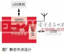
Can be applied to the design through general-purpose I / O (GPIO) or fast I / O (RGPIO). It can replace LCD liquid crystal displays in low-cost solutions. In addition, the waypoint node and the gateway node also do not need LCD liquid crystal display, because a technician can connect the node to view its information through the laptop computer during debugging and maintenance. For all dynamic nodes, audio alarms must be supported.
To save power, the static node is in sleep mode most of the time, and it is only awakened when it finds a car approaching. Solar energy can also be used to provide working power for waypoint nodes and charge their batteries with a 24-hour energy efficiency.
Freescale's advantages
Freescale provides all building blocks for developing a complete ZigBee compatible platform solution, including hardware, software, tools and reference designs. Freescale offers from advanced ZigBee-compatible PiP single-chip solutions to simplified dual-chip hardware solutions that include ZigBee transceivers (radio frequency) and low-power microprocessors (MCUs). In a two-chip solution, the microcontroller should include a liquid crystal controller or two or more SPI interfaces. As one of the features, ZigBee can ensure that information is transmitted on a channel without interfering with other wireless networks, thereby ensuring data integrity.
All modules will include Freescale MC1322x microcontrollers, including the following features:
â— 128KB serial flash; 96KB static RAM; 80KB ROM; IEEE802.15.4 hardware accelerator.
The on-board unit contains these additional on-board parts: an LED array that displays warnings and other important information; a liquid crystal panel (optional) to display information sent by waypoint nodes.
The waypoint node with data recording function will also include SPI flash memory, which can be connected to the onboard MC1322x microcontroller via the SPI interface.
Freescale also provides a fully integrated development environment (IDE) for embedded application development. It also provides BeeKit® wireless connection toolkit for use with IDE, which is a set of development kits that includes a wireless network protocol library, application templates, and sample applications.
Conclusion
In this article we discussed the importance of an effective driver assistance system and how it can help us improve road safety standards. This solution can significantly reduce the risk of drivers and better manage traffic. Compared with other more expensive commercial systems, our ZigBee-based driver assistance system is a cost-effective option that can replace those expensive commercial systems such as GPS, which provides navigation services but does not have any early warning capabilities.
Cat 6 Connectors,Cat6A Connectors,Cat6 Utp Connector,Cat6 Utp Plug
Dongguan Fangbei Electronic Co.,Ltd , https://www.connectorfb.com