OverviewThe CAN bootloader enables programming of the MAXQ7665A microcontroller through its CAN interface. The bootloader also helps designers update / modify the user applicaTIon code for products already deployed in the field.
The CAN bootloader provides a means of writing, reading, and erasing a predefined section of the program flash memory that typically holds the user application code. The user application code resides at 0x4000 to 0x7FFF in the MAXQ7665A.
Two separately compiled modules, the CAN bootloader and the user application code, run in the MAXQ® program memory. These pieces of code exist separately and completely unknown to each other. The modules communicate to each other through known memory space.
The reader of this application note should be familiar with the MAXQ7665A processor (64kB program flash), the CAN controller, and the IAR Embedded Workbench® for the MAXQ.
Both the CAN bootloader code and an example of the user application code are available for the MAXQ7665A here (ZIP).
MAXQ7665A CAN BootloaderThe CAN bootloader, as with the IAR cstartup module, is built and loaded through the JTAG port into the lower part of the program memory at 0x0000. This code searches for a flag value of 0x55AB at location 0x7FFF address. If the code finds the flag, the CAN bootloader jumps to the user application code at 0x4000. If this flag is not found, the CAN bootloader calls the function enter_loader () and waits for the incoming CAN messages.
At this time, global interrupts are disabled because the IGE bit in the IC (Interrupt and Control) register is cleared during code initialization. Therefore, the CAN bootloader polls the IIR (Interrupt Identification) register and the local CAN flag to handle any incoming messages . The CAN bootloader uses Message Center 1 to handle incoming messages; Message Center 2 is used for handling the outgoing messages. (Please refer to the CAN Bootloader Protocol, in Appendix A for these specific commands.)
The next few steps explain the order in which the CAN bootloader and the user code are loaded. The operation of the CAN bootloader and the user code are also shown.
Step 1: Load the CAN bootloader into the lower part of the program memory (Figure 1).
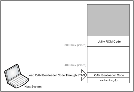
Figure 1. The CAN bootloader is loaded through the JTAG port.
Using the CAN Bootloader to Load the User Application Code in the MAXQ7665AThe IAR Linker File (.xcl) and the IAR cstartup module are modified so that the user application code resides and executes from address 0x4000. Maxim provides both the modified linker and the modified cstartup files here (ZIP). The CAN bootloader loads the user application code, after which the host system sends the "Load Done" command (0x07). When the Load Done command is received by the CAN bootloader, it will put the 0x55AB at 0x7FFF in code space.
Step 2: Load the user application code (Figure 2).
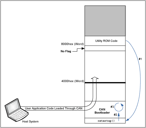
Figure 2. The user application code is now loaded through the CAN bootloader. The CAN bootloader checks 0x7FFF (word) address for a valid flag: (0x55AB). If the flag is not valid, the CAN bootloader code loops and waits for an incoming message. Upon receipt of a valid message, the CAN bootloader responds with a message. In this state the user application code can be loaded at 0x4000.
Step 3: User application is finally loaded and running after a reset (Figure 3).
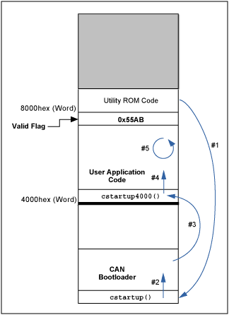
Figure 3. The CAN bootloader checks 0x7FFF (word) address for a valid flag: 0x55AB. If the flag is valid, then the code jumps to 0x4000 to run the user application code.
Reloading / Updating the User Application CodeIt may be necessary to reload / update new user application code into the MAXQ7665A. To accommodate this, the CAN bootloader can be entered from the user application code by calling the function EnterLoader (). At this point the CAN bootloader waits for CAN messages. Figure 4 illustrates the process.
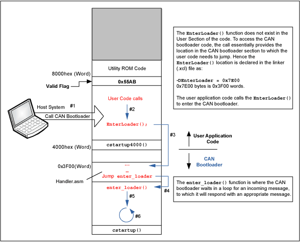
Figure 4. Flow diagram shows how to call the CAN bootloader when the valid flag, 0x55AB, is set at 0x7FFF byte address.
Appendix A CAN Bootloader ProtocolBoot Loader Message Format
Messages between a CAN bootloader host and target use a simple command / acknowledge (ACK) protocol. The host sends a command and within a timeout period the target responds with either an ACK with optional return data or with a NACK with an error code. The first byte of the CAN data area is always a command byte, and up to seven bytes of data can be appended afterward. All multibyte numerical data is formatted as least significant byte first (LSB). As an example, the 16-bit value 0x1234 would be written as 0x34 0x12 with 0x34 at the lowest offset.
Message Format (Byte Fields)
| Command Byte | Opt. Data | Opt. Data | Opt. Data | Opt. Data | Opt. Data | Opt. Data | Opt. Data |
Command Byte Format (Bit Fields)
| ACK | NACK | Reserved | Reserved | Command Nibble (4 bits) |
Example Message (Load Two Words at Address 0x8000)
| 0x02 | 0x00 | 0x80 | 0x34 | 0x12 | 0x78 | 0x56 |
Example ACK Response
| 0x82 |
Example NACK Response (0x83 Is Error Code for Illegal Address)
| 0x42 | 0x83 |
Boot Loader CommandsNine bootloader commands are available to allow erasing, loading, verifying, and signaling of a load complete and for restarting the CPU.
Ping (0x00)
Test message path to target. Zero to seven bytes can optionally be sent and will be echoed back by the target.
Message
| 0x00 | 0x55 | 0x56 | 0x56 | 0x57 | 0x58 | 0x59 | 0x60 |
Response
| 0x80 | 0x55 | 0x56 | 0x56 | 0x57 | 0x58 | 0x59 | 0x60 |
Reset CPU (0x01)
Cause target CPU to perform a hardware reset.
Note: The target will not return an ACK with this command.
Message
| 0x01 |
Load (0x02)
Load into code memory at specified address. Two bytes of address must follow the load command byte, and two to four bytes of data can be written using this command. The target will reset the current address to match the passed parameter and will increment it as the words are successfully written to flash.
The example below loads the values ​​0x1234 to address 0x8000, and 0x5678 to address 0x8001.
Message
| 0x02 | 0x00 | 0x80 | 0x34 | 0x12 | 0x78 | 0x56 |
Response
| 0x82 |
Load Continue (0x03)
Load into code memory at current target address. Two to six bytes of data can be written using this command. The target will increment the target address as words are successfully written to flash.
The example below loads the values ​​0x1234, 0x5678, and 0x9ABC starting at the current target address.
Message
| 0x03 | 0x34 | 0x12 | 0x78 | 0x56 | 0xBC | 0x9A |
Response
| 0x83 |
Read (0x04)
Read code memory at specified address. Two bytes of address must follow the read command byte. The target will reset the current address to match the passed parameter and will increment it as the words are returned to the host. Three words (six bytes) will be returned.
The example below reads three word values, 0x1234, 0x5678, 0x9ABC, starting from address 0x8001.
Message
| 0x04 | 0x01 | 0x80 |
Response
| 0x84 | 0x34 | 0x12 | 0x78 | 0x56 | 0xBC | 0x9A |
Read Continue (0x05)
Read code memory at current target address. The target will increment the target address as words are returned to the host. Three words (six bytes) will be returned.
The example below reads three word values, 0x1234, 0x5678, 0x9ABC, starting from the current target address.
Message
| 0x05 |
Response
| 0x85 | 0x34 | 0x12 | 0x78 | 0x56 | 0xBC | 0x9A |
Erase (0x06)
Erase bootloader accessible code area. This command will require over 1.3 seconds to complete.
Message
| 0x06 |
Response
| 0x86 |
Load Done (0x07)
Notify the loader that the loaded image is good and can be booted on next CPU startup. The boot loader will write a tag at the end of the program memory to designate a good load, and will vector to the startup address of the loaded application when the CPU is restarted.
Message
| 0x07 |
Response
| 0x87 |
Get Current Target Address (0x08)
Returns the current target address. This will be the next address used to write or read code space using the Load Continue (0x03) or Read Continue (0x05) command.
The example below shows the target returning a current target address of 0x8005.
Message
| 0x08 |
Response
| 0x88 | 0x05 | 0x80 |
ErrorsFlash Write (0x80)
Unable to write to flash. Flash controller returned an error.
Flash Verify (0x81)
Unable to write to flash. The data read back did not match the data written.
Flash Already Programmed (0x82)
Unable to write to flash. Flash requires an erase before this address can be programmed.
Illegal Address (0x83)
Address parameter is outside the bounds of the allowed code space.
Odd Number of Bytes (0x84)
Only word wide (16-bit) data can be written. Make sure that input data is an even number of bytes.
Missing Parameters (0x85)
Command requires parameters following the command byte.
Invalid Command (0x86)
An invalid command was sent by the host.
IAR Embedded Workbench is a registered trademark of IAR Systems AB.
MAXQ is a registered trademark of Maxim Integrated Products, Inc.
Drum type Rice Cooker
Features
This type rice cooker is famous with drum type appearance, which is easy operation and easy clean.
There are two type of inner pot , one type called white pot which is without non-stick but cheaper price .another one called non-stick pot is polished with emery, Also there are two type non-stick with different price ,it`s depending on different demands to use.
And the inner pot cannot be burned on the stove, which will make the pot transfigured and bad contact with the heating plate. While cooking , the heating plate or the fuse is most likely to be burned for the bad contact of the inner pot and the heating plate, Besides, make sure to dry the pot before putting into the outer shell of the rice cooker ,or else the drops of water flowing on the heating plate, will make the heating plate rusted.
Applications
Many peoples are used drum type rice cooker for congee and soup, some of peoples are prefer to use this type rice cooker for steaming.
Drum Rice Cooker,Drum Shape Rice Cooker,Electric Drum Rice Cooker,Multifunctional Drum Rice Cooker
Guangzhou Taipeng Electrical Appliances Technology CO., LTD. , https://www.kettles.pl