Temperature acquisition digital tube display system based on LM35 and 51 single chip microcomputer

With the rapid advancement of electronics and sensing technologies, temperature measurement and control have become essential in various fields such as civil engineering, industrial automation, and aerospace. Small, low-power, cost-effective, and highly reliable temperature sensors are increasingly in demand. In real-world applications, temperature is a critical environmental factor, and accurate and timely monitoring is crucial for maintaining efficiency and safety. This paper presents a temperature acquisition and display system based on the AT89S51 microcontroller and the LM35 temperature sensor. The system features high sensitivity, strong anti-interference capability, and stable operation, making it suitable for a wide range of applications. 1. System Structure and Working Principle 
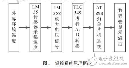
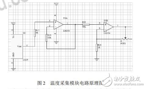
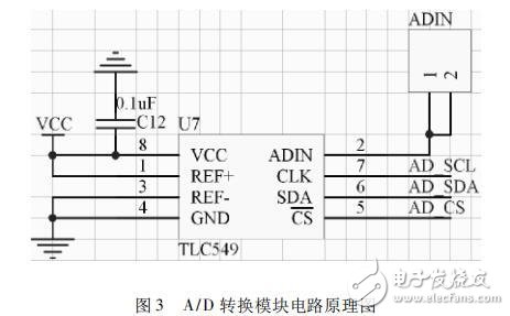
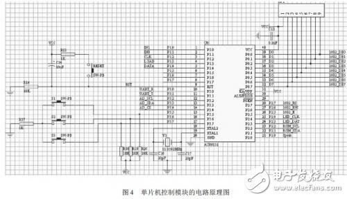
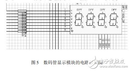
The temperature acquisition and display system consists of several key modules: a temperature sensing module, an analog-to-digital (A/D) conversion module, a microcontroller unit (MCU) control module, a digital tube display module, and a download module. The working principle involves collecting ambient temperature using the LM35 sensor, amplifying the output signal with an LM358 operational amplifier, converting the analog voltage into a digital value via the TLC549 A/D converter, and then displaying the measured temperature on a digital tube controlled by the AT89S51 microcontroller. The system operates as an open-loop control system, with the block diagram shown in Figure 1.

2. Core Hardware Circuit Design The core hardware design includes the temperature acquisition module, A/D conversion module, MCU control module, digital tube display module, and download module. 2.1 Temperature Acquisition Module As the first stage of signal input, the sensor plays a vital role in determining the overall performance of the system. The LM35 temperature sensor was chosen for its high precision and linear output. It provides a voltage proportional to the Celsius temperature, with a 10mV per degree Celsius change. The LM35 requires no external calibration and offers ±0.25°C accuracy at room temperature. To enhance the signal strength, the output from the LM35 is amplified by a factor of 10 using an LM358 amplifier circuit before being sent to the A/D converter. The schematic of this module is illustrated in Figure 2.

2.2 A/D Conversion Module The A/D conversion module uses the TLC549, a CMOS-based 8-bit serial A/D converter. It supports a supply voltage range of 3V to 6V and has a conversion time of 17μs. The chip uses a single clock signal and a chip select (CS) pin to control data input and output. With a maximum input clock frequency of 1.1MHz, the TLC549 ensures fast and accurate sampling. The schematic for this module is shown in Figure 3.

2.3 MCU Control Module The AT89S51 microcontroller was selected for its low power consumption, high performance, and built-in 8KB flash memory. Unlike the 8031, which requires external memory, the AT89S51 allows for easier integration and programming. It supports online programming, enabling real-time debugging and system optimization. The microcontroller controls the digital tube display, ensuring that the measured temperature is clearly visible. The schematic for the MCU control module is presented in Figure 4.

2.4 Digital Tube Display Module The digital tube display is a crucial component of the system, allowing users to monitor temperature values in real-time. This module uses standard 8-segment digital tubes driven by the microcontroller. The display updates dynamically, ensuring clarity and readability. The schematic for the digital tube display module is shown in Figure 5.

Hospital Elevator

Hospital Elevator,Hospital Lift,Bed Elevator In Hospital,Hospital Bed Elevator

ZHONG HAN INTERNATIONAL TRADE CO., LTD , https://www.cck-ht.com