A multi-layer ceramic capacitor (hereinafter referred to as a patch), an indispensable component in electronic equipment, often exhibits a "twisted crack" phenomenon. This article is mainly about the principle of the generation of twisted cracks and the method to prevent the generation of twisted cracks.
What is a twisted crack? 01First, let's look at the shape of the torsional crack in Figure 1. Twisted cracks are cracks (cracks) caused by distortion. Distorted cracks are hard to find from the outside of the patch. Therefore, we cut the patch as shown below to observe the image of the section.
From this, we can find that the twisted crack is characterized by cracks from the one end of the external electrode to the diagonal direction.

Representative example of a crack
Principle of the generation of twisted cracks 02Why do you have twisted cracks? This is because the patch is soldered to the board. Excessive mechanical force is applied to the board, causing the board to bend or age, resulting in twisted cracks. Turn the board over and you will see the following.
As shown in Figure 2, the board is stretched over and the underside is shrunk. Due to the above stretching, the copper pads move to the left and right.

Circuit board deformation and stress map
As the pad moves, the solder also moves or deforms. After the solder is deformed, the external electrodes of the patch move and deform, and the tensile stress concentrates on one end of the external electrode of the patch. When the tensile stress is greater than the strength of the patch dielectric, cracks occur.

The principle of twisted cracks
The effect of twisted cracks 03When the twisted crack extends from one end of the lower external electrode to the upper external electrode, the capacity is lowered, so that the circuit exhibits an open state (open). Therefore, even if the crack is not very serious, if the internal electrode of the patch is reached, the organic acid and moisture in the flux may intrude through the crack gap, resulting in a decrease in insulation resistance performance. In addition, the voltage load becomes high, and when the current flow rate is too large, the worst case may cause a short circuit.
Once a twisted crack occurs, it is difficult to remove it from the outside, so in order to prevent the occurrence of cracks, it should be controlled not to apply excessive mechanical force.
What is the amount of distortion? 04In order to avoid the occurrence of twisted cracks, it is best not to apply excessive mechanical force on the site where the product is produced. So what is the way to visualize excessively applied mechanical forces? . One effective method is to measure the amount of distortion. Below, let's first introduce what is the amount of distortion.
Distortion refers to the amount of change in unit length when a load is applied to an object.
The stretch ratio at this time is the amount of twist.
ε=ΔL/L ε: amount of distortion; L: length before applying force; ΔL: length of deformation
For example, when a 1000 mm rod is stretched left and right and becomes 1001 mm, 1 mm/1000 mm = 0.001 ST = 1000 μST.
How to prevent the generation of twisted cracks? 05In order to prevent the occurrence of twisted cracks, we need to take countermeasures from both board design and process management. First, introduce the countermeasures for process management. First measure the amount of distortion introduced earlier, and then manage the amount of distortion in the process. Let's set the standard amount of distortion. If the setting is too small, it needs to be strictly managed. If the setting is too large, a twist crack will occur. The general setting values ​​are: 500μST for customers who produce life safety products, and 1000μST for customers who produce ordinary consumer products. Even for boards with the same degree of distortion, the stress of the components will vary depending on the type and thickness of the board used. Therefore, the customer should judge the established standards according to experience.
The amount of distortion in each process is measured below. Murata has used the items surveyed in the past to summarize which operations will produce distortion cracks. The most important thing is to manage the process.
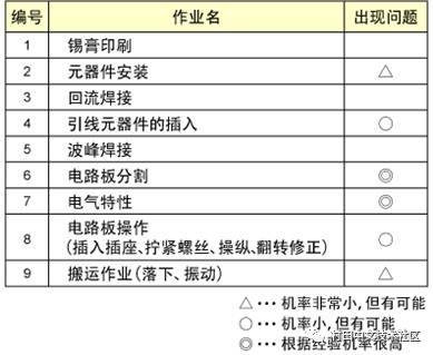
Table 1 Installation and the possibility of twisting cracks
Regarding the process exceeding the setting standard, the amount of distortion can be controlled by improving the equipment, improving the work, and the like.
The main precautions in design: 1. The distance between the board end, the screw hole and the connector
(For example, set a reasonable distance of 10mm or more.)
2. Configuration
(In general, the dividing lines are preferably set in parallel. Like the corners of the board and the bent part of the L-shaped board, it is best not to place the patch where it is easy to concentrate stress.)
3. Selection of dividing line
(Setting the line is better than punching)
4. Width of the pad
(The size of C is preferably smaller than the W (width) of the patch)
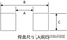
Pad size
5. Configuration design mode
(To prevent the printed circuit board from being deformed due to reflow, it is best to design it in copper foil mode)
6. Using resin external electrode products
(Resin external electrode products can be used in consideration of large distortion.)
Above and so on.
Htn Panel,Positive Transflective Lcd Display Module,Htn Monochrome Lcd Display,Htn 7 Segment Lcd Display
Huangshan Kaichi Technology Co.,Ltd , https://www.kaichitech.com