As shown in Figure 1, on the DragonBoard 410c development board, the GPIO port is reserved through the interface. The user can easily access the GPIO port of the DragonBoard 410c through the pin header or cable during the development test. The connection is set to control the peripherals. You can also view the GPIO details by downloading the DragonBoard 410c GPIO PDF and the instruction manual. The GPIO port design of the 410c board is detailed in the SchemaTIcas_DragonBoard.pdf file in the 410c package. As shown in Figure 1 below, the detailed design of the GPIO hardware interface J8 of the development board is given. Through this figure, the GPIO external interface connection of the entire 410c development board can be known.

Figure 1 DragonBoard 410c external GPIO port lead-out interface J8 connection schematic
According to the above schematic diagram, DuPont line can be connected on the board. In the test, two GPIO ports of GPIO_36 and GPIO_12 are selected as the control. GPIO12 controls the LED light, GPIO_36 is used to receive the key signal, and the detection switch is pressed. Next, the switch changes state once every time the LED is pressed, and the hardware connection of the entire control circuit is as shown in FIG. 2 .
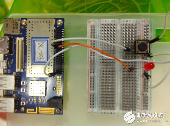
Figure 2 DragonBoard 410c button control LED light hardware connection diagram
Second, the program design1) In the Linux environment, use the vim editor to create the project program file key_led_test.c, which is the main file of the test project. The command is as follows:
Mkdir key_led_test
Vim key_led_test.c
The basic principles of controlling the LED and detecting the button signal through the GPIO port are as follows:
First, you need to import the GPIO port used. After the import, the GPIO port can be read and written. The function code of the function imported into the GPIO port is as follows:
Int Export_GPIO(int gpio) {
Int fd;
Char buf[MAX_BUF];
Sprintf(buf, "%d", gpio);
Fd = open("/sys/class/gpio/export", O_WRONLY);
If(fd < 0)
Return -1;
Write(fd, buf, strlen(buf));
Close(fd); return 0; }
}
Then read and write data to the GPIO port, and the implementation function and code of the read and write are as follows:
Int Write_GPIO(int gpio, int value) {
Int fd; char buf[MAX_BUF]; //Set the direcTIon of the GPIO to output
Sprintf(buf, "/sys/class/gpio/gpio%d/direcTIon", gpio);
Fd = open(buf, O_WRONLY); if(fd<0)
Return -1;
Write(fd, “outâ€, 3);// Set out direcTIon
Close(fd);
Sprintf(buf, "/sys/class/gpio/gpio%d/value", gpio);
Fd = open(buf, O_WRONLY);
If(fd<0)
Return -1; // Write the GPIO value
Sprintf(buf, “%dâ€, value);
Write(fd, buf, strlen(buf));
Close(fd); return 0;
}
Int Read_GPIO(int gpio, int *value) {
Int fd; char val;
Char buf[MAX_BUF];
Sprintf(buf, "/sys/class/gpio/gpio%d/value", gpio);
Fd = open(buf, O_RDONLY);
If(fd<0)
Return -1;
// Read the GPIO value
Read(fd, &val, 1);
*value = atoi(&val);
Close(fd); return 0;
}
Finally, after completing the GPIO read and write operations, you need to export the GPIO port. The implementation functions and code are as follows:
Int UnExport_GPIO(int gpio) {
Int fd; char buf[MAX_BUF];
Sprintf(buf, "%d", gpio);
Fd = open("/sys/class/gpio/unexport", O_WRONLY);
If(fd < 0)
Return -1;
Write(fd, buf, strlen(buf));
Close(fd); return 0;
}
The above is the core function and implementation process of the GPIO port. Then, using the call of these core functions and the simple logic of design, the state of the button on the connection 410c board can be detected. The function of the button detection is as follows: :
Int get_key_status(int Key){
Int tmp=1;
Int time=0;
Write_GPIO(Key, 1) ;
Do{
Delay_ms(10);
If(Read_GPIO(Key, &tmp)==0){
Time++;
}
Else return -1;
If(time>=100){
Break; / / Press the time exceeds 1s, indicating that the completion of a press, exit detection.
}
}while(!tmp)
If(time>=50){ // greater than 0.5s, the button is pressed, not interfered or accidentally pressed
Return KEY_DOWN;
}
Else return KEY_UP;
}
After the button detection is completed, the LED can be controlled according to the button. The LED control is to light the LED by outputting a high level, and outputting a low level to extinguish the LED. The implementation function is as follows:
Int set_led_status(int Led, int status){
If(Write_GPIO(led, status)==0){
Return 0;
}
Else return -1;
}
After completing the state reading of the KEY and the state control function of the LED based on the read/write function of the GPIO, the two functions can be conveniently used to construct the program for controlling the LED by the button. The core code of the .c is as follows:
#include
#include
#include
#include
#include
#define MAX_BUF 10
#define GPIO_A 36
#define GPIO_B 12
#define KEY_DOWN 1;
#define KEY_UP 0;
#define LED_LIGHT;
#define LED_EXTING;
Int Export_GPIO(int gpio);
Int UnExport_GPIO(int gpio);
Int Write_GPIO(int gpio, int value);
Int Read_GPIO(int gpio, int *value);
Int get_key_status(int Key);
Int set_led_status(int Led, int status);
Int main(void) {
Int KeyStatus=KEY_UP;
Int LedStatus=LED_EXTING;
Ret = Export_GPIO(GPIO_A);
If(ret != 0)
Printf("Error exporting GPIO_%d", GPIO_A);
Ret = Export_GPIO(GPIO_B);
If(ret != 0)
Printf("Error exporting GPIO_%d", GPIO_B);
Printf("you can press key to change LED status");
While(1) {
KeyStatus=get_key_status(GPIO_A);
If(keyStatus!=-1) LedStatus=KeyStatus;
Else{
Printf("get_key_status erro!");
Return -1;
If(-1== set_led_status(GPIO_B, LedStatus)) {
Printf("set_led_status erro!");
Return -1;
}
}
Ret = UnExport_GPIO(GPIO_A);
If(ret != 0)
Printf("Error UnExporting GPIO_%d", GPIO_A);
Ret = UnExport_GPIO(GPIO_B);
If(ret != 0)
Printf("Error UnExporting GPIO_%d", GPIO_B); return 0;
}
The above is the use of the 410c development board to achieve GPIO operation in the Linux operating system environment, through the GPIO port to read the button information to achieve LED control.
Third, the program compiles and runsIn the Linux environment, you can compile the platform program through the arm-linux-gcc cross-compilation tool, generate executable program files, and then download them to the development board. The compilation commands are as follows:
Arm-linux-gcc -o key_led_test key_led_test.c
After the compilation is complete, generate the key_led_test file, and execute the following command to change its permissions, making it an executable file:
Chmod 777 key_led_test
Finally, execute key_led_test to control the LED light on the board by pressing the button.
Various products of Jewelry USB Flash Drive, including Jewelry USB Flash Drive Gift Box, Jewelry USB Logo, Jewelry USB Stick, Jewelry Usb Memory Stick, Jewelry Usb 2.0 Memory Flash Stick Pen Drive and so on. We also providing product images and basic parameters with each Jewelry USB Flash Drive and Jewelry USB Flash Drive OEM 3D inside engraved Logo;

Jewelry USB Flash Drive is An ideal way to store all your pictures, documents, music and videos. Jewelry USB Flash Drive Can act as a wonderful gift for your friends and families and A great way to distinguish your masses of USB flash drives from each other as our cute USB come in a variety of variations for every day use.

- Compatibility: Desktop, Laptop, Macintosh, Tablet, Speakers all with USB1.0 and 2.0.
- Operating System : Windows7/Vista/XP/2000/ME/NT/98,Linux (Sometimes incompatible with Mac OS 9.X/Linux2.4)
- Fine choice for advertisement allow to print LOGOs and advertisement.
- Very Low Power Consumption, durable solid-state storage.
- Small and exquisite design brings much convenience.


We are a professional Chinese manufacturer of Jewelry USB Flash Drive, and look forward to your cooperation!
Jewelry Usb Flash Drive,Heart Shape Jewelry Usb Flash Drive,Jewelry Diamond Usb Flash Drive,Usb Flash Drive
Reteck Electronic Co., Ltd. , https://www.reteck.com