This is a circuit diagram of household inverter power supply with excellent performance. The material is easy to take and the output power is 150W. The design frequency of this circuit is about 300Hz, the purpose is to reduce the volume and weight of the inverter transformer. Output waveform square wave. This inverter power supply can be used for home lighting in the event of power failure, fluorescent lamps for electronic ballasts, household appliances for switching power supplies, etc.
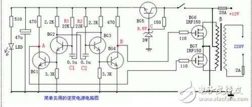
Capacitors C1 and C2 are made of polyester capacitors, triodes BG1-BG5 can be used with 9013:40V 0.1A 0.5W, and BG6-BG7 can be used with field effect transistors IRF150: 100V 40A 150W 0.055 ohms. Do not connect the power tube first, measure the voltage of point A and point B to the ground, adjust R1 or R2 so that the voltages of the two points A and B are the same, so that the output square wave is symmetrical and the quiescent current is also the least. Pay attention to the following items during installation: BG6 and BG7 must be soldered with a well-grounded soldering iron or cut off the power supply. The high current should be connected with a thick wire with a diameter of 2.5 mm or more, and the wiring should be as short as possible. The battery voltage is 12V and the capacity is 12AH or more. The power tube should be equipped with a suitable heat sink, for example, with a 100*100*3MM aluminum plate. If you want to increase the power, increase the power of the same type of power supply in parallel, and increase the power of the transformer accordingly.
Inverter design calculation method
The choice of transistors: in view of safety factors, to have a certain safety factor. The empirical information is as follows:
Dc Power Supply voltage: transistor collector withstand voltage BVCEO
6~8V≥20~30V
12~14V≥60~80V
24~28V≥80~100V
Calculate the collector current of the transistor: ICM (A) = output power P (W) ÷ input voltage V (V) & TImes; efficiency. The input voltage is the power supply voltage. Efficiency is related to the circuit chosen, typically between 60 and 80 percent. Core cross-sectional area: S (square centimeter) = k & TImes; square root of transformer rated power, k is selected in the table below

The choice of transformer core: Amateur production is not strict with the core of the transformer. However, the silicon steel sheet is preferably thin and brittle, or a ferrite core. The enameled wire is made of high-strength, and the winding wire needs to be tightly wound by a winding machine. Strictly level the silicon steel sheet when it is placed. The relationship between the voltage across the primary winding and the cross-sectional area of ​​the core and the operating frequency can be expressed as follows: V=4.44&TImes;10-8SKFBN
Where S is the cross-sectional area of ​​the core (square centimeters);
K - gap coefficient of silicon steel sheet (0.9 ~ 0.95);
F - inverter operating frequency (Hz);
B - saturation magnetic flux density (T);
N - the number of turns of the coil (circle);
V - the voltage (volts) of the primary winding.
The value of K is related to the thickness of the silicon steel sheet and the gap between the sheet and the sheet. The tighter the core layer is, the higher the K value is, the general K is 0.9. The operating frequency of the inverter is mainly determined by the selected core. The silicon steel core is used, and the operating frequency of the inverter is lower than 2KHZ. Different ferrite cores are used, and the working frequency is between 2KHZ and 40KHZ. If the operating frequency exceeds the natural frequency of the core, the high frequency loss is very serious. The saturation magnetic flux density B is different for different specifications of silicon steel sheets, and is generally between 0.5 and 1.4T. Silicon steel sheet is thin and brittle, so the magnetic properties are good, B can be larger; silicon steel sheet is thick and soft, the magnetic properties are poor, B can be smaller. The B of the ferrite core is about 0.2 to 0.5T.
The primary winding is wound in two wires. When winding the transformer, people are accustomed to using the number of turns per volt. This can be expressed by the following equation: N = 2500/SKFB per volt, where K is the gap coefficient of silicon steel sheet (0.9 ~ 0.95) ; wire diameter D (mm) = 0.715 & TImes; square root of I.
It adopts high-quality battery monomers grouped and screened and designed by special mechanical structure to assemble all ranges of built-in BMS batteries. Our Battery Management System(BMS) are specially designed for the rechargeable batteries of battery packs used for automated guided vehicles(AGVs), electric vehicles(EVs) Batteries, electric forklifts, electric pallet trucks and Other material handling equipment.
BMS For Nickel Cadmium Battery
Batterie Management System,Smart Battery Management System,Nickel Cadmium Battery Management System,Bms For Nickel Cadmium Battery
Xinxiang Taihang Jiaxin Electric Tech Co., Ltd , https://www.agvchargers.com