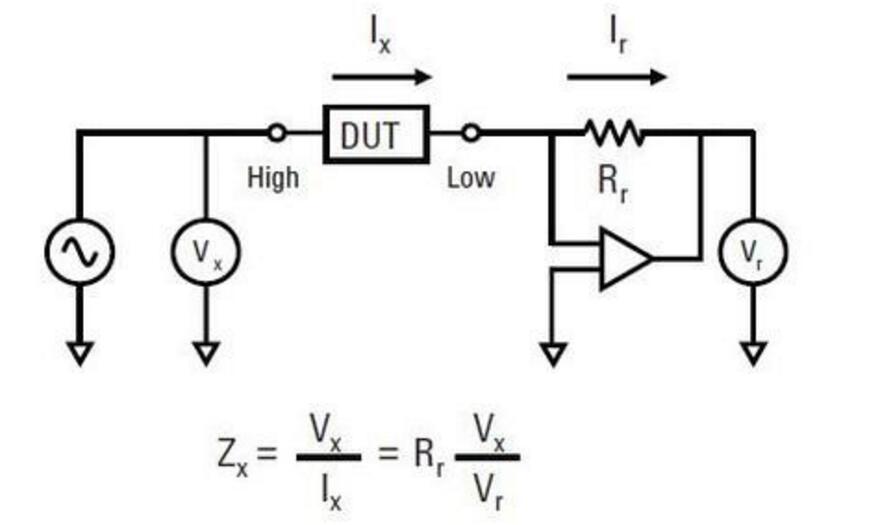
**LCR Tester Measurement Principle**
Both Vx and Vr are vector voltmeters, while Rr is an ideal resistor. The self-balancing bridge mechanism ensures that when the Device Under Test (DUT) is connected to the circuit, the amplifier’s negative feedback creates a virtual ground at the OP input. This setup allows Vx to accurately measure the voltage across the DUT, with the low potential of the DUT set to 0. Meanwhile, Vr and Rr work together to measure the current Ix flowing through the DUT, enabling the calculation of Zx, the impedance of the component under test.
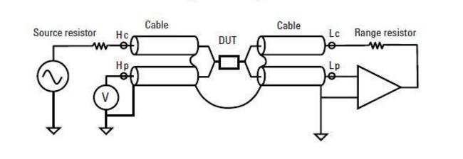
The HP4275 has four test terminals: Hp, Hc, Lp, and Lc, where 'c' stands for current and 'p' for potential. The configuration of the Guard (ground) can significantly impact measurement accuracy due to differences in parasitic effects. To improve accuracy, it's crucial to place Hp, Lp, Hc, and Lc as close as possible to the DUT. Reducing the loop area and magnetic flux of the test current Ix is also essential. By using Guard and cable shielding, the loop area can be minimized, which helps reduce interference. Although this may increase the capacitance between the signal lines and ground, it doesn’t affect the test results but lowers mutual capacitance between signal lines.
The parasitic impedances (Zhg, Zlg) of the Guard and cables do not influence the measurement. When the bridge is balanced, the voltage across Zlg is zero, so no current flows through it, and it doesn't shunt the current through Rr. Similarly, any shunt from Zhg does not affect the voltage measured at Hp.
**LCR Tester Measurement Steps**
LCR testers are commonly used to measure the characteristics of inductors and capacitors. The general steps involved in the testing process are:
1. Set the test frequency.
2. Adjust the test voltage or current level.
3. Choose the desired test parameters, such as Z (impedance), Q (quality factor), LS (series inductance), LP (parallel inductance), CS (series capacitance), CP (parallel capacitance), D (dissipation factor), etc.
4. Perform instrument calibration, typically involving open and short circuit calibrations. High-end models may also require load calibration.
5. Select the appropriate test fixture.
6. Apply fixture compensation to eliminate errors.
7. Place the DUT on the fixture and initiate the test.

**Main Functions of the LCR Tester**
Digital bridges are widely used by metrology departments for verifying and transmitting impedance standards. They are also commonly used in various industries for measuring impedance components. Many digital bridges come with standard interfaces that automatically adjust the measurement based on the accuracy required. These devices can also be integrated into automated test systems for quality control during production.
Capacitors, inductors, and resistors are among the most frequently used passive components in electronic design. Their performance directly impacts the overall functionality of the circuit, making accurate measurement essential. While DC resistance can be measured with a multimeter or a dedicated resistance tester, inductors and capacitors require AC measurements. An LCR tester uses AC signals to determine the impedance, which includes both magnitude and phase information—represented as a complex number or vector.
Unlike simple DC resistance, which only reflects the size of the resistance, impedance (Z) captures both the magnitude and the phase difference between voltage and current. This makes LCR testers essential tools for precise and detailed characterization of electronic components.
Power Storage LiFePO4 Battery Solar Energy Systems For Home
|
S/N
|
Item
|
Content
|
|
1
|
product type
|
Modular 48V large-capacity energy storage power system
|
|
2
|
Module model
|
48V200Ah
|
|
3
|
Weight
|
430kg
|
|
4
|
System capacity
|
200Ah*Parallel number(200~2000Ah)
|
|
5
|
Module dimension
|
19-inch standard cabinet width, thickness 5U, depth 480
|
|
6
|
Maximum continuous charge and discharge current
|
0.75C
|
|
7
|
Installation method
|
Pedal models, seat bucket models, etc.
|
|
8
|
IP rating
|
Module IP20, system power box can be customized IP65
|
|
9
|
Service life
|
10 years or 3000 cycles
|
|
10
|
Operating temperature range
|
Temperature: -20~60℃ Humidity: ≤85%RH
|
|
11
|
product description
|
The product is positioned as an energy storage power supply system, in accordance with the ultra-long storage/cycle life, modular design, can be connected in parallel according to the required system capacity, and can realize battery intelligent monitoring and
battery management through RS485 communication or CAN communication, and inverter power supply/ UPS power supply and other equipment are perfectly compatible and can be widely used in various 48V energy storage power systems |
|
14
|
certificate
|
MSDS,ISO9001,CB,UN38.3
|
Energy Storage Lithium Battery Cbinet For Home
Jiangsu Zhitai New Energy Technology Co.,Ltd , https://www.zttall.com