Today, automotive safety systems are driving the development of MEMS inertial sensor technology and are being used in several large areas. A large number of applications related to automotive safety systems have contributed to significant investments in MEMS manufacturing technology, packaging concepts, quality assurance systems, and design innovations. These investments have resulted in cost-effective and more reliable solutions that have also made profits in many other areas. Includes the gaming platform (Wii Remote) and many mobile handheld applications. In addition, MEMS sensors have found other increasingly industrial applications, including shop floor safety systems. Among them, equipment position sensing, collision detection, and prevention of rollover when the crane is lifted are all examples of workplace safety systems, all of which benefit from MEMS accelerometers.
The task of the shop safety system is to detect potentially hazardous operating conditions, but not to affect normal operation. The most important of these is the accuracy of the sensing scheme used to detect hazardous operating conditions. Like most other technology solutions, MEMS accelerometers also have a trade-off between cost performance. For automotive and commercial applications, modest performance can be achieved at the lowest cost. However, for some industrial applications, such as shop safety systems, higher accuracy is required. In this application, reliability, convenience, and component cost of the solution are all important.
With the advent of highly integrated and more sophisticated accelerometer products, system designers need to understand how parts are calibrated because it determines whether they are purchasing these calibrations or developing their own calibration procedures. This article will discuss the calibration process for a two-axis accelerometer and focus on the most common sources of error.
Purpose and necessity of calibrationFor many MEMS inertial sensor users, calibration provides an opportunity for their sensing solutions to improve performance and compromise system cost, as shown in Figure 1. The figure shows only the general relationship, and the performance goal is driven by the end system performance requirements that can add value to the user.
For example, high precision means that the anti-flip system does not require overcompensation when determining the limits of the crane. Optimal optimization of the level of accuracy can extend the service range of the crane or lift heavy loads without the risk of rollover. Therefore, the bottom line for optimizing performance in a safety sensing system is the ability to add value to the total system.
The cost increases associated with calibration include direct material costs (such as ADC, microcomputer, PCB complexity, and labor costs) and investment costs (calibration equipment fixtures and engineering development costs), but these costs will be expected for system products. The volume is diluted. The obvious goal of any calibration process is to achieve higher value performance while controlling the associated costs.
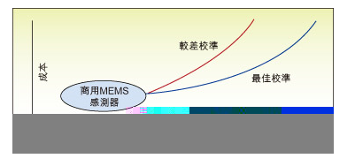
Figure 1: For many MEMS inertial sensor users, calibration provides an opportunity for their sensing solutions to improve performance and compromise system cost.
In the comparison of performance versus cost in Figure 1, the difference between a well-used calibration scheme and a poor scheme is plotted. By identifying and reducing risk efforts, it will be possible to determine the cost of a given level of performance improvement. It only needs to move an error from the blue area to the red area.
The development of a MEMS calibration solution can be divided into four simple phases:
1. Establish performance goals
2. Determine calibration requirements
3. Design calibration process
4. Implement calibration rules
Establishing a valuable performance goal for accelerometer calibration will set the tone for the entire development process. First, these goals will guide the choice of sensors, and second, will guide the analysis process, which will determine the behavior that needs to be calibrated and ultimately determine the complexity of the calibration process. This is critical because excessive pursuit of higher than required will result in excessive cost and development time.
So obviously, this requires developers to understand the impact of the accelerometer sensing system on the final system performance goals. While this early investment may seem inconvenient, it leads to better performance and more innovation opportunities. This discussion will focus on areas that need to be considered when the calibration combined error is less than 1%.

Figure 2: Typical accelerometer calibration circuit
Error Sensitivity Analysis: A typical circuit used to provide calibrated accelerometer performance is shown in Figure 2. This error analysis determines the impact each device has on the overall system accuracy target. Each device has behavioral factors that need to be considered. In addition to MEMS accelerometers, amplifiers, A/D, multiplexers, and passive components will exhibit certain deviations. Gain, linearity, noise, power, and temperature will exhibit independent behavioral characteristics. For sensor performance. These need to be carefully considered.
This section will list the common threats to the above performance goals and give a quick way to determine the impact of the circuit while avoiding specific circuit analysis. For simplicity, sensitivity analysis was focused on sensor performance in the discussion. It is assumed that the contribution of the remaining circuit elements is small. The ideal equation for any linear sensor that includes a MEMS sensor is:

In IEEE-STD-1293-1998, a broad modeling scheme describing the error behavior of a typical MEMS accelerometer is presented. The following equation gives a simple relationship describing many common errors:

The sensor signal conditioning circuit will include several components that affect the equation. Some common sources of error for these devices are listed below:
1. NENS accelerometer
2. Amplifier
3. Passive components
4. A/D
Each device will contribute to sensitivity (gain), bias (deviation), linearity, noise, power-dependent behavior, and temperature-dependent characteristics. The calibration discussed here will focus on the sensor. However, the graphic guidelines also apply to other circuits.
Since the combined error is less than 1%, we can quickly review the specifications of commercial MEMS sensors. For example, a leading accelerometer should have the following indicators:
Sensitivity: +950mV/g to +1050mV/g, equivalent to 5%
Offset: 30mg (typical), equivalent to 3% (1g system)
100mg (maximum), equivalent to 10% (1g system)
In this case, the offset and sensitivity must be considered first in the calibration process because both exceed the 1% integrated error target.
A reliable calibration source for low g accelerometers is gravity. The easiest way to use gravity is by using the industry standard drop test given in IEEE-STD-1293-1998. In the drop test, an excitation with a range of +1 g is applied to the device under test (DUT).
This low excitation level cannot be used for the drop test of an accelerometer with a full scale range of less than 20 g because the applied calibration excitation is equal to or greater than 5% of full scale. Beyond this range, linearity, resolution, noise, and other range-related properties will become more influential, preventing the desired accuracy from being achieved. For calibration, the full scale range allows for a 4-point drop test instead of a multi-drop test, but a multi-point test can be used for linearity error calculations.
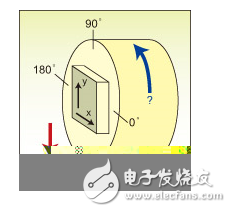
Figure 3: Four-point drop test plot.
A simplified diagram of the four-point drop test is shown in Figure 3. Here, the DUT is vertical. The X axis of the DUT points to a 0° tilted horizontal axis. Record the X-axis output of the DUT. Then the DUT is rotated by 90°, 180° and 270°, respectively, and the X-axis output of each point is recorded, so it corresponds to four measurement positions.
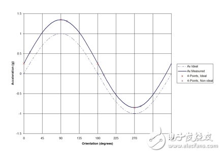
Figure 4: Four-point drop data output
Since the DUT is rotated, the sensor output of the X-axis will be a sinusoidal function of the tilt angle, as shown in Figure 4. The difference between the actual curve and the ideal curve is due to the offset and sensitivity error of the accelerometer. By analyzing the data on each 90° rotation increment, these behaviors can be characterized and isolated. The total sinusoidal offset can be calculated by averaging the 0° and 180° points. The measured value of the 1 g-stimulated accelerometer output provided by gravity is obtained by subtracting the data at the 270° point from the 90° data point.
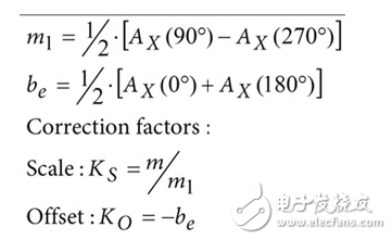
The basis of these relationships is the precise alignment of the 0°, 90°, 180°, and 270° positions. It also depends on the precise alignment in the vertical direction of the full 1 g excitation.
Since the pursuit of "perfect" measurement sensitivity is neither practical nor affordable, it is important to understand how sensitive each potential error (introduced by the calibration system itself). Determining the impact of each error will help reduce the risk of violating key performance criteria.
The initial alignment angle absolute error refers to the starting position error. This home position error will affect the sensitivity but will not affect the offset. This effect can be isolated without affecting other sensitivities and can be described by:

For a 1% sensitivity error, the initial alignment error must be less than 8°. If the sensitivity error is higher, such as 0.1%, the initial alignment error must be less than 0.8°. However, the absolute angular error is equivalent to the two positions of 0° and 180°, so the alignment error does not affect the offset. This is an advantage of using a 4-point measurement scheme. Once the actual offset is obtained, the initial alignment error can be calculated:

If the sensitivity accuracy target is required, the calculated alignment error can be substituted back to the above error equation and used to quantify the calibration factor. In this way, the pressure at which the initial starting angle must be set to a precise 0° is eliminated.
Error type and calculationRelative Alignment Error: This error is defined as the deviation between each measurement step and the ideal 90° step value. Offset calibration will have a higher sensitivity to this error. The following relationship can be used to calculate the offset error introduced by the alignment error:

Corresponding to the 1% offset accuracy target, or 10mg in a 1g range application, the alignment accuracy must be better than 0.57°. For a 0.1% offset accuracy, or 1 mg, the relative alignment accuracy must be better than 0.057°. Although the initial alignment error angle is easy to calculate, for high-precision calibration, relative angular sensitivity requires strict position control.
Deviation from axial error: Deviation from axial error refers to the total amount of change in the axial direction relative to the horizontal axis. If the rotating device is completely vertical, the rotating axis is horizontal. Deviation from the axial error will affect the sensitivity error, and the way it affects is very similar to the method of initial alignment.
The reminder here is to pay attention to the change of gravity acceleration, because the external excitation of 1g is not necessarily accurate 1g. The impact is exactly twice the impact of local gravity, and it varies with theoretical gravity. Theoretical gravity is also affected by latitude, sea level elevation, moon-sun gravity fluctuations, and nearby supermass.
Mechanical vibration: Any form of vibration can be converted into linear acceleration and introduce errors into the calibration. Mechanical isolation using granite blocks or air-isolated tabletop structures will help reduce errors or use data filtering to eliminate vibration-induced defects.
Accelerometer Sensitivity Error: The two most important factors affecting accelerometer sensitivity characteristics are supply voltage and temperature. The four-point drop can also be used to characterize the behavior of the accelerometer over the expected power and temperature range. The linear approximation scheme requires four-point drop data to be acquired at the extreme positions (minimum and maximum) of each parameter. These data can be used to extrapolate the incremental correction factor based on accuracy requirements. If nonlinear behavior is found, more data points can be added while increasing the order of the curve fit.
Power Supply Error: Certain accuracy requirements will require characterization of the effects of power supply variations. When needed, the same four-point drop test can be used at different power levels to acquire the data needed for the appropriate curve fit. The complexity of the curve fit is independent of the accuracy goal and the nature of the error itself. The result will be a series of calibration coefficients for each power supply condition.
Temperature error: In order to maintain a 1% error in temperature changes, the temperature coefficient for sensitivity and offset should be considered.
Sensitivity = 0.3% (typical range, -40 ° C to +125 ° C)
Offset = 0.1mg / °C (typical)
For quick estimates, these values ​​can be doubled (assuming 2 times) combined with the following:
The combined temperature error is:
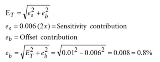
If the maximum acceleration measurement is 1g, the ratio can be used to calculate the range over which the temperature can vary while maintaining the 1% integrated thermal error target:

It is possible to apply correction factors calculated according to this calibration process to many digital platforms. Examples include microcontrollers, digital signal processing, field programmable gate arrays (FPGAs), and other programmable logic devices. The processor resources required to correct the formula will affect the choice of processor, but in many industrial systems, the processor has more demanding requirements. The mathematical functions required for calibration are relatively simple: (1) eliminating offset/offset errors by adding operations, and (2) eliminating quantization errors with multiple operations.
In applications, changes in the operating conditions of industrial systems will affect the bias and sensitivity of MEMS accelerometers. The most common operating conditions that affect these characteristics are the supply voltage and ambient temperature. The supply voltage can vary up to 10%, and each industrial system has its own temperature range.
If the change in operating conditions exceeds the permissible range of system performance, a four-point drop test is required under various operating conditions in order to plot the error characteristics and generate a table of calibration factors. The final completion of these coefficients is as shown in Figure 5. There are three variables in the calibration table in this case, including a set of variables for the operating conditions that are out of tolerance, which can be used for frequency response or various other conditions.
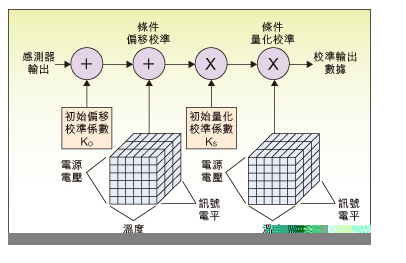
Figure 5: Calibration signal flow.
in conclusionThe most important thing in deploying accelerometer calibration is to build valuable performance goals. For the risk areas identified and discussed in this article, developers should be aware that calibration is not arbitrary, but there are still plenty of value-added opportunities, if the ultimate goal is clear. In fact, R&D performance goals are not limited to engineering, but include schedule risk (loss of revenue), performance risk (not meeting customer requirements), and high cost (loss of market). While the impact of performance is fundamental, consider the investment required to achieve this performance and continue to calibrate, all of which help engineers make better overall decisions because the issues they consider are an eternal issue. - The relationship between manufacturing and purchase.
We are professional audio manufacturing company that makes a variety of speaker with bluetooth, including bluetooth portable speaker, bluetooth speakers outdoor, small speaker bluetooth, light bluetooth speakers, waterproof speakers etc.
With full turnkey service from product design to delivery, and every step in between.
From sophisticated custom audio systems to 'off-the-shelf' speaker drivers, iTopnoo has been saving our customers time, effort, and money.
To constantly offer clients more innovative products and better services is our consistent pursuit.
Best Portable Speakers,customizable bluetooth speaker, Custom jbl speakers, speaker wholesalers
TOPNOTCH INTERNATIONAL GROUP LIMITED , https://www.mic11.com