Note: The simulation is about the words "imitation" and "true". How to integrate the two words together, you need to pay attention to many details. This article introduces two very important points.
Background introduction
In the field of high-speed digital, we often refer to the electrical part between the transmitter and the receiver as the channel. Channel performance is one of the key factors affecting signal quality. We can use ADS to evaluate the channel performance. The typical simulation step is to use the EM simulation engine (ADS mometum/SIPro/EMPro, etc.) to extract the S parameters of the evaluation channel (you can also obtain the S parameters), and then apply the S parameters. Time domain simulation, then analyze the time domain simulation results. An eye diagram is one of the most common analysis objects.
However, the details of the S parameters need to be noted to ensure that the channel performance can be accurately obtained in the time domain simulation. This document analyzes some of these details.
Channel time domain simulation
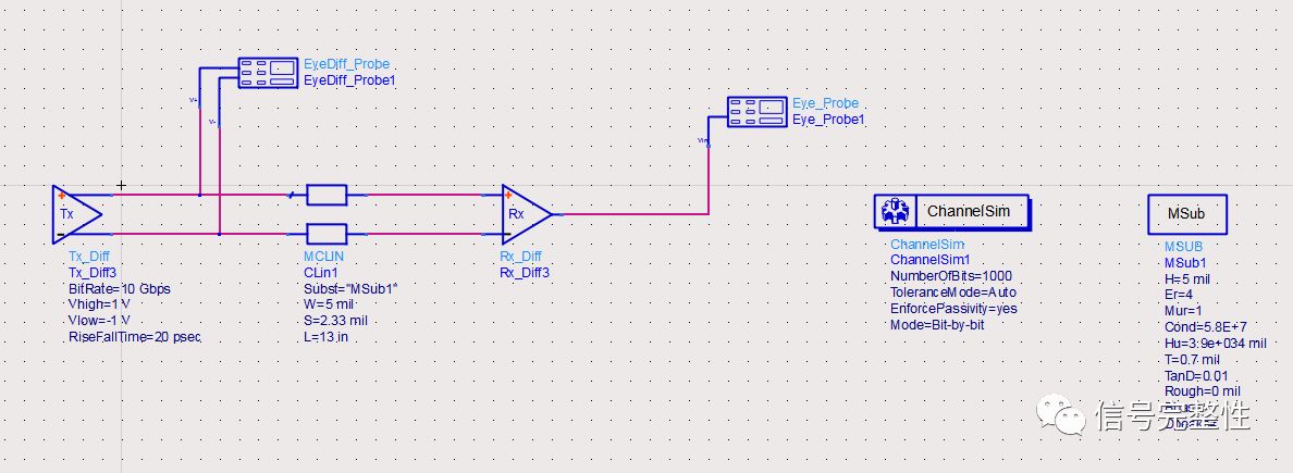
Let's first look at a case. The following figure shows a circuit for time domain channel simulation. It uses a simple channel, a pair of differential lines, and the differential signal lines are connected to the ideal transmitter chip model and receiver model. The signal rate is 10Gbps and the rise and fall time is 20ps. Simulate the following circuits:

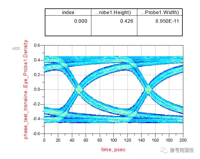
The obtained eye diagram is as follows:

This eye diagram is very good. The eye width is 89.5 ps and the eye height is 426 mV. Next, we conduct an experiment to extract the S parameters of the transmission line:
Extract the S parameters of the transmission line
The S-parameter solver is used to extract the S-parameters of the differential line, and the extracted frequency range is 0-20 GHz, stepping 1 GHz:

After the simulation is complete, use the data extraction tool to convert the simulation results into an S-parameter file:

Then, using the S parameter obtained in the previous step, replace the transmission line and perform channel simulation. The simulation circuit is as shown below:

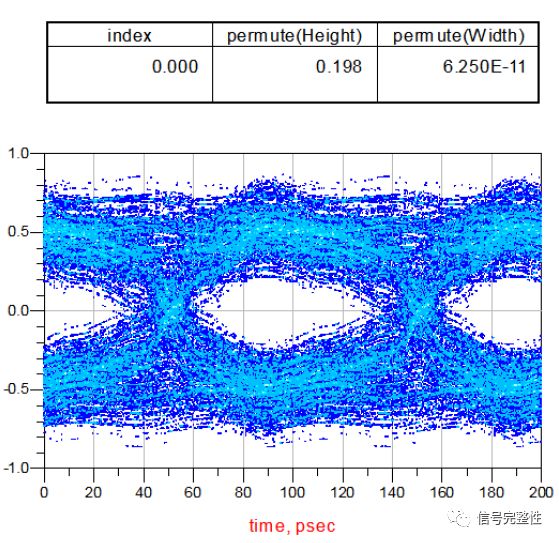
Obtain the eye diagram results as follows:

The eye width is 62.5 ps and the eye height is 198 mV. Obviously, the results are quite different from those obtained with the original transmission line simulation. The eyesight margin becomes smaller, and the noise and jitter are much larger. In order to clarify the problems, the following experiment was done. Set the step to 0.1 GHz, extract the S parameters, replace the obtained S parameters with the previous S parameters, and obtain the eye diagram results as follows:

The eye width is 93.5 ps and the eye height is 397 mV. After the step size is reduced, the results are greatly improved and are very close to the most primitive results.
Since the results have improved, consider continuing to reduce the step size to 0.01 GHz. After extracting the S parameters, the channel simulation is performed. The eye diagram is as follows:

The eye width is 89.5 ps and the eye height is 403 mV. Obviously, the results are closer to the most original results. Of course, when the step is finer, it is closer to the most original result, but it also brings the efficiency of the simulation to a lower level.
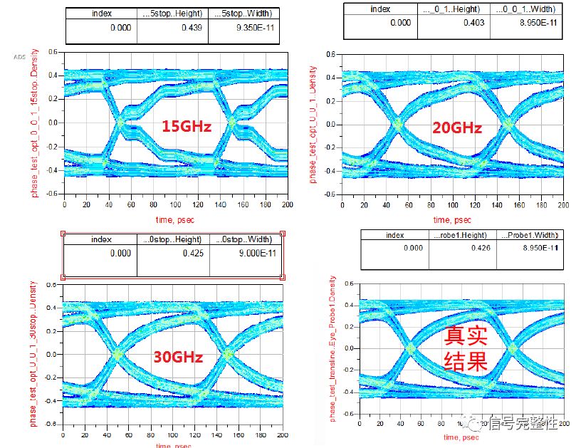
The previous changes are the steps when extracting the S parameters. Then, we analyze from another angle, that is, under the condition of 0.01 GHz, change the bandwidth of the extracted S parameters and extract 15 GHz, 20 GHz and 30 GHz respectively. The S parameters are taken into the channel for simulation and the results obtained are as follows:

The eye width and eye height of several simulated eye diagrams are as follows:
| Eye width (ps) | Eye height (mV) | |
| Original (10GHz) | 89.5 | 426 |
| 15GHz | 93.5 | 439 |
| 20GHz | 89.5 | 103 |
| 30GHz | 90 | 425 |
From the above analysis of the results, it can be seen that when the bandwidth of the extracted S parameter reaches 3 times the bandwidth, the result is closer to the most original result.
in conclusion:
1. When the frequency is determined, as the frequency step increases, the performance of the s-parameter model is closer to the original result;
2. After obtaining the step determination of the S parameter, as the bandwidth of the extracted S parameter increases, the performance of the s parameter model is closer to the original result;
3. As can be seen from the previous comparison, when the simulated data rate is 10 Gbps, if the S-parameter model is required to be almost the same as the original performance, when the S-parameter is acquired, the S-parameter simulation is set to 0.01 GHz step, 30 GHz frequency. The actual extraction process can achieve this precision through appropriate internal interpolation or adaptive algorithms.
Ic Interface Analog Switches,Interface Direct Digital Synthesis,Interface Drivers Receivers Transceivers,Ic Chip Integrated Circuit
Shenzhen Kaixuanye Technology Co., Ltd. , https://www.iconlinekxys.com