1 Introduction
Fieldbus technology is a hot topic in the world today. The all-digital control system based on fieldbus is the mainstream of the 21st century automation control system. PROFIBUS-DP is an optimized high-speed, low-cost communication connection designed for communication between automatic control systems and device-level distributed I/O. The PROFIBUS-DP module can replace expensive 24V or 0-20mA parallel signals. Line for high speed data transmission in distributed control systems. PROFIBUS-DP is mainly used in the field device level. Its response time is from several hundred to several hundred ms, the data transmission rate is 9.6kbit/s to 12Mbit/s, and the data capacity transmitted is up to 244 bytes per message. The transmission medium is shielded twisted pair or optical cable, which is widely used in building automation, hydropower management and industrial process automation control systems.
2 hardware design of PROFIBUS-DP communication interface in soft start controller
In the PROFIBUS-DP hardware interface circuit design of the soft start controller, the SCM3 + RS485 drive scheme of the single chip + dedicated integrated chip is adopted.
2.1 SPC3 Brief
SPC3 (SIEMENS PROFIBUS CONTROLLER) is an optimized intelligent PROFIBUS-DP slave station that integrates the data transmission and reception functions of the PROFIBUS-DP physical layer and can independently process the PROFIBUS-DP protocol. Inside the SPC3 are RAM, mode registers, status registers, interrupt registers, and various buffer pointers and buffers. SPC3 has 8 data lines and 11 address lines, of which 8 data lines are multiplexed with address lines, and can be connected to 80C32, 80C166, 80C196, HC196 and other single-chip microcomputers. SPC3 integrates 1.5KB dual-port RAM as the interface between SPC3 and software/program, which can automatically adjust the 9.6K to 12M baud rate.
2.2 PROFIBUS-DP communication interface hardware design
The connection between the PIC16F877 and the PROFIBUS-DP network consists of a protocol chip SPC3 and RS-485 driver circuit of a PROFIBUS-DP network. The PROFIBUS-DP interface is mainly composed of a processor interface and a serial bus interface.
Processor interface circuit shown in Figure 1: 80C32 through the P0 port and P2 port to expand the external memory, the SPC3 internal dual-port RAM as their own external RAM, through the read and write of the dual-port RAM to complete the SPC3 initialization and related data Exchange. In the figure, P1 refers to the soft start controller designed with dual PIC16F877. As a communication slave station, PIC16F877 integrates SPI interface, can be combined with protocol chip SPC3, and MAX485ESA completes the connection to the PROFIBUS-DP bus network.
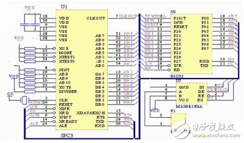
Figure 1 processor interface circuit
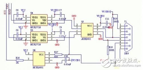
Figure 2 serial bus interface circuit
The SPC3 chip transmits a data signal (TXD) through a request transmission signal (RTS), receives a data signal (RXD), and is connected to a bus transceiver ADM1485 through a high-speed optocoupler HCPL7720 to form a serial bus interface. As shown in Figure 2, although the SPC3 has integrated the data transfer function of the physical layer, it does not have the RS-485 drive interface, so the RS-485 drive circuit is added. At present, there are only a few driver chips that can meet the 12M baud rate. There are SN65ALS176, SN75ALS176, ADM1485, etc. The ADM1485 is used in this system. In addition, in order to avoid the influence of signals on the bus on the circuit, the SPC3 and RS-485 bus drivers are used. Optical isolation between the circuits. The isolation device of TXD and RXD signals is selected from Hewlett Packar's 12M high-speed optocoupler HCPL7720, and the signal isolation device of RTS is HCPL0601.
3 communication interface software design
The PROFIBUS-DP ASIC chip SPC3 integrates the PROFIBUS-DP protocol and can handle the PROFIBUS-DP state mechanism, so the 80C32 does not have to participate in the PROFIBUS-DP state machine. The main task of the 80C32 is to properly configure, initialize, and process various packets of SPC3.
The software operation of SPC3 mainly includes two parts: initialization of SPC3 and interrupt processing of SPC3. The main program and the interrupt program flow chart are shown in Figures 3 and 4, respectively.
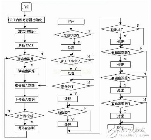
Figure 3 main program flow chart Figure 4 interrupt program flow chart
SHENZHEN CHONDEKUAI TECHNOLOGY CO.LTD , https://www.siheyidz.com