Medical electron linear accelerator is used for tumor treatment equipment, which is often called radiotherapy. The main principle is to use high-energy X-rays to kill cancerous cells. This paper elaborates on the dosimeter system of this type of machine and runs it on the actual equipment of our hospital. A failure instance is analyzed for help, and I hope to help my peers.
The WDV E-6 accelerator is a standing wave electron accelerator. The dosimeter system plays an important role in the accelerator. Its work directly affects the output dose and affects the patient's therapeutic effect and even life-threatening.
For this reason, the Vectra Accelerator adopts a dual-channel independent dosimeter system to ensure the stability of its work. Since the channel one and the channel two circuit are identical, the following only describes the working principle of the channel one as an example.
1. System overviewAs the ray passes through the ionization chamber, the ionization chamber produces current signals (A, B, and C, D) proportional to the intensity of the ray and is sent to two separate channels of the dose circuit. When the monitored dose is equal to the preset on the console, the channels act together to terminate the bundle. When the channel fails for some reason, channel 2 is preset to be 30 units higher than the console, terminates the beam, and warns the operator that the machine has failed through the fault light and buzzer. The two-channel monitoring dose is digitally displayed on the console, and the emitted dose is consistently stored on another independent mechanical counter. The maximum number of doses is preset on the mechanical counter, so that even if both channels fail, the machine The counter is terminated after the preset dose has been reached, ensuring patient safety and thus achieving a three-level protection of the dose. The system also monitors the symmetry of the emitted rays in real time. If the symmetry exceeds the standard, the beam will be terminated immediately. The specific system block diagram is shown in Figure 1.

The ionization chamber comprises two independent sealed penetrating ionization chambers, each having a set of signal electrodes (A, B in the upper chamber, C, D in the lower chamber), and signal electrodes A, B and C, D placed vertically. For stable operation of the ionization chamber, it must be provided with a stable -500V DC voltage and monitored. When the voltage is abnormal, the machine is protected and a fault indication occurs. The two ionization chambers are respectively rectified by 180VAC-500VDC. Circuit power supply. When the X-ray passes through the ionization chamber, it interacts with the gas molecules in it, and the positive ions are attracted to the reference electrode, and the electrons are attracted to the signal electrode, so the signal electrode actually becomes a constant current source, and the radiation is generated during the pulse. The charge output is proportional to the intensity.
3. Channel control circuitThe principle is as shown in Figure 2. The ionization chamber signal A is applied to IC 1, and B is applied to IC2. IC1 and IC2 form the basic charge-voltage conversion circuit. IC1 and IC2 are output through 6-pin, and the outputs of IC1 and IC2 are passed through R14. R15 is injected into pin 2 of IC3. IC3 completes the addition of two signals. The output of IC3 is sent to the dose adjustment unit consisting of IC5 through R27. The dose can be calibrated by adjusting R31. The output of IC5 is sent all the way through 1X6-17. The dose rate table shows the dose rate of the radiation, and is sent to the 1 pin of IC9 through R35. The IC9 and IC10 form a voltage pulse generator, and the voltage proportional to the dose rate given by the integration circuit is converted into a pulse signal, and the pulse signal is The frequency is proportional to the input voltage. This pulse signal is isolated by the iris IC12A and sent to the 1:100 divider consisting of IC11A and IC11. The pulse signal is divided and output from the 1X6-52 to the counter. The displayed value is exactly the dose in "Rad". The BCD code output from the counting unit drives the MU1 digital display on the console. The comparison circuit compares the counter output with the console finger wheel setting dose value. When the count reaches an amount of the thumbwheel setting value, the comparator 1 is given a dose completion signal to the power beam path, the beam termination machine.
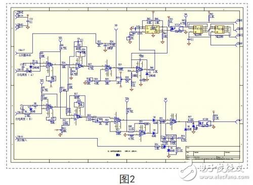
IC4 completes the subtraction of the two signals and compares the signals of the ionization chamber (A, B). This signal is output to the interlock protection circuit through the dose symmetry detection circuit composed of IC6, IC7, IC8, optical IC12B, and 1X6-7. In the case that the ray field is asymmetrical, the symmetrical detection circuit gives a signal de-symmetric chain circuit corresponding to the degree of asymmetry. When the signal exceeds the specified range, the symmetrical chain circuit will terminate the machine beam and illuminate the console. Symmetrical (SYM) fault light on the upper.
Troubleshooting example:Symptom 1: The channel 1 and channel 2 dose values ​​are inconsistent, and the difference is very large.
Analysis and testing:
First, use the dosimeter to monitor the dose of the accelerator. The channel 2 is normal. Use the oscilloscope to detect the channel-XJ1 test point. At this time, compare the waveforms of the two channels and find that it is caused by the latter circuit. Monitor the XJ3 test point and adjust the R31 to find the XJ3. The point voltage does not change, indicating that the IC5 is damaged, try to change IC5, adjust the R31 calibration dose, and the accelerator returns to normal.
Symptom 2: When there is no beam, there is a dose indication on the channel, and channel 2 is normal.
Analysis and testing:
The channel 1 and channel 2 integral plates are reversed, and the fault phenomenon is unchanged. It indicates that the fault is in the front stage. The oscilloscope is used to monitor the output of the 1X6-27 ionization chamber. It is found that the fault is not related to the beam, indicating that the ionization chamber may be damaged or the signal line is open. Cause, try to lift the machine head and tighten the output terminal of the ionization chamber with a wrench, and troubleshoot.
Symptom 3: Console "SYM" when launching
The light is on and the machine cannot be bundled.
Analysis and testing:
This fault indicates that the machine has a symmetrical fault or its protection circuit is faulty. When the beam is sent, the XJ5 test point is detected as high level, indicating that the protection circuit is controlled. The XJ4 test point is also detected as high level and the voltage is unstable. The voltage of the foot is also unstable. It is found that the voltage of 15V is unstable in the 7th leg of IC4, indicating that the 15V terminal is in poor contact. Try to disconnect the circuit board with pure alcohol and reinsert it. The “SYM†fault is cleared and the machine returns to normal.
4 ConclusionThe medical accelerator dose system is complex in design, with many interlocking protection lines, and the corresponding failure rate is relatively high. This requires high requirements for engineers. It is necessary to be familiar with the principle of this part and carefully observe the equipment failure phenomenon, due to the importance of the dosage system. Sex, remember not to mess with the chain protection, a slight accident will cause a major accident, you must carefully handle each link, the dose system must be corrected after the dose, so as to ensure the normal and safe operation of the system.
Capillary Manometer,Capillary Tube Manometer,Capillary Thermometer,Vacuum Manometer
ZHOUSHAN JIAERLING METER CO.,LTD , https://www.zsjrlmeter.com