The sci-fi robot uses the idle old Android phone as the brain of the robot.
This is not only the environmental concept of waste utilization, but also makes the function of the Cyber ​​Robot more bright by making full use of the powerful computing power and hardware resources of the Android phone:
1) No need for an external USB camera, directly use the high-definition camera of the Android phone, and video H.264 compression encoding through the powerful GPU of the mobile phone for network transmission.
2) Using the networking capabilities of Android phones, wifi, 3G, 4G can be networked. And integrated with the spirit of P2P cloud connection, you can connect robots from anywhere in the world.
3) Using mobile computing power to achieve speech recognition, using natural voice to control robot movements.
4) Using mobile computing power, based on the OpenCV software library, implement gesture analysis and face tracking.
Principle introduction:
In addition to the Android phone as the brain, the Netling robot also uses the Arduino microcontroller to control the motor servo and connect the sensor module.
As the brain of the Android phone and Arduino MCU is communicated through the Bluetooth serial port (such as the common HC-06 on the market), the communication protocol is very simple, based on the string format, Arduino periodically sends sensor readings to Android phones, Android The phone sends a control command to the Arduino.
The remarkable feature of the Netling robot is that it can remotely remotely control the robot from a remote location with the mobile phone control terminal and the computer control terminal, and view the camera image in real time. The implementation of this function is based on the Principal P2P cloud connection platform, which is the underlying core technology that NetEase has accumulated over the years. As long as the robot is connected to the network, it can be connected to the robot from any corner of the world. There is no need to set up a router port, no dynamic domain name mapping is required, and the NAT intranet is completely automatically penetrated.
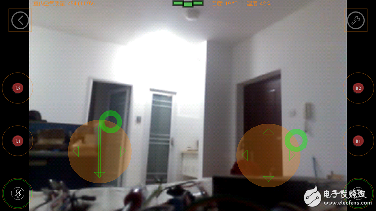
The control software of the cyborg robot is the cybernet control. It is equivalent to a "remote control handle with video return". There are some handle buttons and 2 virtual joysticks. The UI interface is like this:
Robot gesture recognition and face tracking are developed based on OpenCV. The source code is in the jni directory of the Android code. It just takes a framework and invites the makers to improve and expand. . .
Raw materials and components
1) A cartoon tissue box with a cartoon pet appearance (available on Taobao)
2) 1 universal mobile phone clip (available on Taobao)
3) 1 set of 3D printing parts of Netling robot
4) Arduino control board + Bluetooth small board 1
5) L298N motor drive module 1
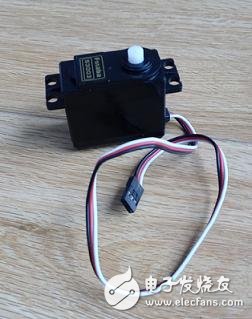
6) 1 standard steering gear
7) Battery voltage sensor module 1
8) One rechargeable lithium battery
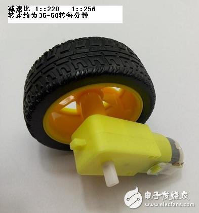
9) 65mm wheel + motor (not too fast, about 50 rpm) 2 sets
10) One inch caster 1
11) 1 switch
12) M3x30mm long screws 4, M3x25mm screws, M3x8mm screws, some self-tapping screws, 2 long copper screws, M3 nuts
13) Several DuPont lines, some conductive lines

tool
Electric iron, electric drill, 502 glue, electric tape, pliers, screwdriver, knife
Assembly step
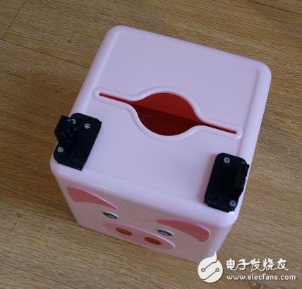
First, the upper and lower parts of the tissue box are uncovered and divided into the upper box and the lower bottom cover, first using the box.
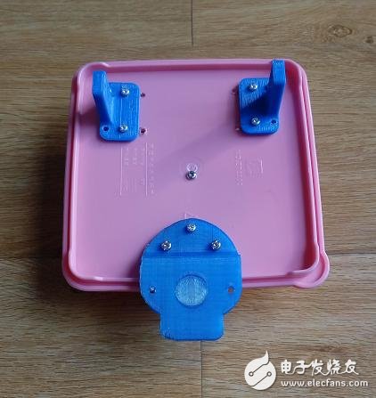
Fix the 3D printed parts--the mobile phone clip left bracket and the mobile phone clip right bracket with the self-tapping screws to the box, as shown below, note that the left and right brackets should be fixed to the edge of the box, otherwise the back steps will not have enough width to place the phone clip. .
Prepare the standard steering gear, size 40.7*19.7*42.9mm
Use 2 self-tapping screws to fix the steering gear to the 'phone holder left bracket', as shown below:
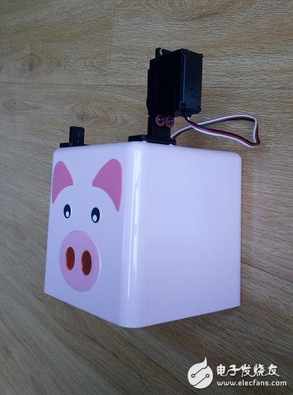
Look at the front,
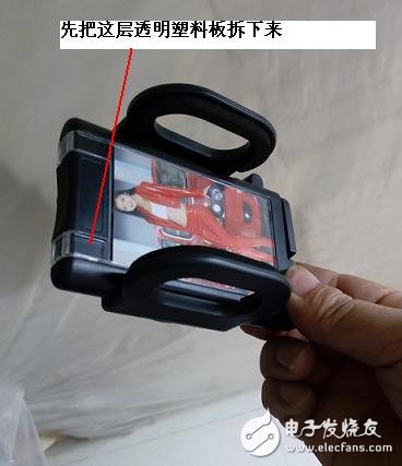
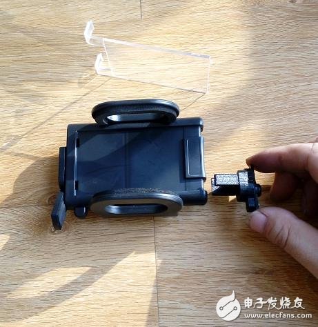
Let's start with the universal mobile phone clip. First remove the transparent plastic plate inside, and use it behind the transparent plastic plate. Don't throw it.
Adjust the position of the two movable plastic pieces on one side, and the lower piece will be fixed to the 'right holder of the mobile phone holder'.
Insert the 3D print--'phone clip coupling' into the groove of the phone holder as shown below:

Note that the one-swing arm of the steering gear is fixed to the 'handphone clamp coupling' with a self-tapping screw. This one-hand swing arm is to be inserted into the steering shaft of the steering gear.
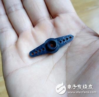
Prepare to place the phone clip on the left and right brackets. One side is: a pendulum arm is inserted into the steering shaft of the steering gear.
On the other side: use 2 self-tapping screws to secure the 'mobile phone holder right bracket' and the movable plastic piece under the phone holder.


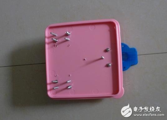
At this point, the box part is ready. Start to get the bottom cover part.
Secure the two 3D print 'chassis wheel brackets' to the bottom cover with M3x25mm long screws.
Then the 3D print 'chassis caster bracket' is also fixed to the bottom cover.

The opposite is like this:
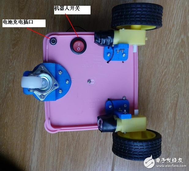
Drill 2 holes in the bottom cover with an electric drill:
a diameter of 20mm for the switch;
Another 9mm in diameter for charging interface;
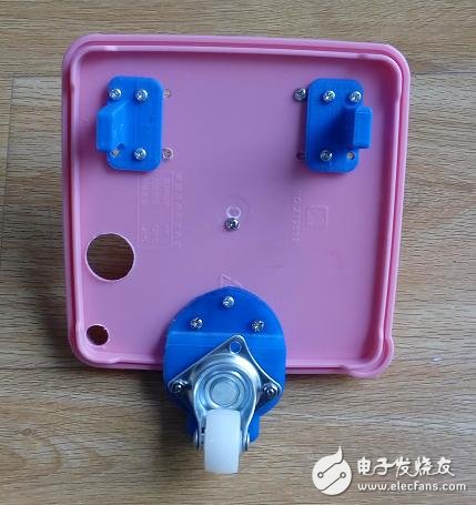
Then use the M3x30mm long screw to install the two wheels (with motor) on the 'chassis wheel bracket', and the two pairs of motor wires are led from the bottom cover perforation to the inside;
Install the universal wheel to the 'chassis caster bracket' with M3x8mm screws.

Screw the 3D print 'battery holder' inside,
Then install the L298N motor driver board as shown below:

Install the two long M3 copper column screws, and then attach the previously removed mobile phone clip transparent plastic plate to the copper column screw and fix it with 2 nuts.
The screw holes on the transparent plastic plate can be made with circuit iron or electric drill.

Screw the "Arduino+Bluetooth" control panel to the transparent plastic plate.
Install the lithium battery into the 'battery holder':
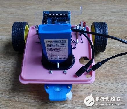
Look at it from another angle:
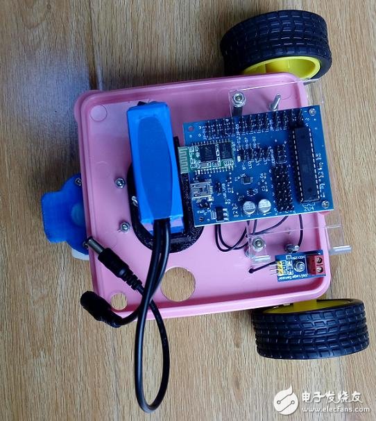
Install the battery voltage detection module board:

Install the DC female wire of the lithium battery into the charging hole of the bottom cover and fix it with 502 glue;
Install the 20mm diameter switch into the switch hole of the bottom cover.

At this point, the bottom cover part is also installed. (Of course, if you want to connect the sensor module to the Arduino control board, you can uncover the box connection at any time!)
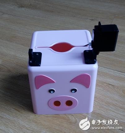
Prepare to cover the upper and lower parts of the tissue box:

OK, the physical structure is assembled, and you're done! ! !
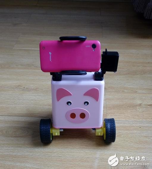
Finally, you can install 2 steering gears on the left and right sides, fix 2 small arms, and the robot will look even more cute.
Electronic circuit module connection
When you assemble the physical structure of the sci-fi robot, the circuit connection is easy. Prepare some 3Pin DuPont lines and conductive wires, and connect the corresponding circuit modules according to the following circuit diagram:
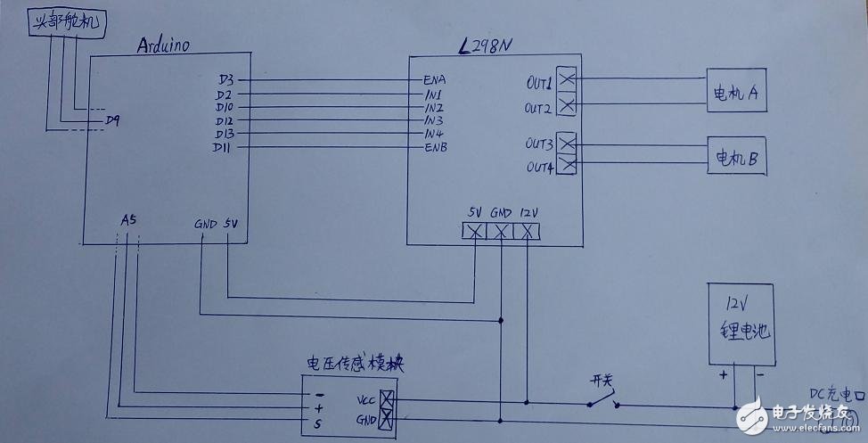
It can be seen that the power supply of the Arduino control board is output by the 5V of the L298N motor control board.
The voltage detection module is connected to the analog port A5 of the Arduino; the head servo is connected to the digital port D9 of the Arduino;
You can also extend the connection to more sensors later, such as:
The gas sensor MQ2 is connected to the analog port A4, and the temperature and humidity sensor is connected to the digital port D8.
These are pre-defined in the Arduino program code and need to correspond to the code:
++++++++++++++++++++++++++++++++++++++++++++++++++++++++++++++++++++++++++++++++++++ ++++++++++
#include "Servo.h"
#include 《dht.h》
/ / Definition of analog IO port and digital IO port
#define PIN_UNDEFINED 255
#define PIN_A_VOLTAGE 5 //Battery voltage sensor
#define PIN_A_MQX 4 //Gas sensor, MQ2, MQ135
#define PIN_D_SERVO_V 9
#define PIN_D_SERVO_H PIN_UNDEFINED
#define PIN_D_SERVO_L 5 //PIN_UNDEFINED
#define PIN_D_SERVO_R 6 //PIN_UNDEFINED
#define PIN_D_DHT 8 //PIN_UNDEFINED //DHT11 temperature and humidity sensor
#define PIN_D_RELAY PIN_UNDEFINED //One way relay
#define PIN_D_RED PIN_UNDEFINED //Infrared body sensor
#define PIN_D_LEDA PIN_UNDEFINED //LED indicator A
#define PIN_D_LEDB PIN_UNDEFINED //LED indicator B
//PT2272 Recv, D0-"D3 is implemented with analog IO port, because the digital IO port of Arduino UNO is not enough
#define PIN_D_2272VT 4
#define PIN_A_2272D0 0
#define PIN_A_2272D1 1
#define PIN_A_2272D2 2
#define PIN_A_2272D3 3
//315M, 433M RF Send, control intelligent switch, smart socket, electric curtains. . .
#define PIN_D_315SEND 7 //PIN_UNDEFINED
#define PIN_D_433SEND PIN_UNDEFINED
/ / left and right three directions of the barrier sensor pin definition
#define PIN_D_BIZ_C PIN_UNDEFINED
#define PIN_D_BIZ_L PIN_UNDEFINED
#define PIN_D_BIZ_R PIN_UNDEFINED
/ / L298N motor drive board control pin
//The servos use the 9th PWM, and the L298N uses the 10th and 11th PWMs, which will cause the 10th PWM to fail! ! !
// motor A
#define dir1PinA 2
#define dir2PinA 10
#define speedPinA 3
// motor B
#define dir1PinB 12
#define dir2PinB 13
#define speedPinB 11
++++++++++++++++++++++++++++++++++++++++++++++++++++++++++++++++++++++++++++++++++++ ++++++
[Brightness Upgrade]Compared with the T6, our Led Flashlight brightness has increased by 20% and the illumination distance has increased by 50%. Being made by the world famous CREE Advanced Wick Chip L2, our flashlights can easily light up an entire room or focus in on objects up to 1800 feet away in the dark.
[Power Upgrade]The Rechargeable Flashlight uses the latest 18650 battery (battery included), USB charging, can be used for more than 6 hours after being fully charged. Our battery has been certified so that you do not have to worry about safety issues.
[2-in-1 Upgrade]To use it with ease, we combine far-light and short-light in one mode, compared with the zoomable, the 2-in-1 is brighter and further, effortless one-handed operation to get bright and long shot light whenever you need it, ideal for use around the house, dog walking, camping.
[5 Modes and Waterproof]The flashlight has 5 useful settings: high / medium / low / Strobe/ SOS. In addition, thanks to the anti-slip ring at the tail, the flashlight is IP65 waterproof and can withstand most extreme weather such as storms and heavy rain.
[Super Durable & Secure]Because of aluminum alloy, it is so powerful that it can be used to prevent disasters and other undesirable conditions. Multiple certifications (FCC, CE, RoHS) and customer service support provided, an ideal gift for your friends and family.
Rechargeable Flashlight
Best Rechargeable Flashlight,Rechargeable Torch Light,Rechargeable Head Torch,Rechargeable Tactical Flashlight
Ningbo Wason Lighting Technology Co.,Ltd , https://www.wasonlight.com