In handheld devices, the use of liquid crystal displays is becoming more widespread. Since the LCD itself is not illuminating, it requires a powerful light source to provide backlighting for clear display of information. Such a light source is very power hungry, and usually the power consumption of the liquid crystal display often accounts for more than 60% of the total power consumption of the system. Take the group's 7-inch screen as an example. Usually, the backlight consumes 2.5W, while the LCD consumes only 0.825W. It can be seen that the power consumption of the backlight source is quite high in the entire power source. If the system is running at full power without the display, the battery energy of the system will be quickly consumed. Therefore, it is very necessary to adjust the backlight of the LCD to reduce the energy consumption of the system when the display is not used.
In addition, due to the change of the working environment of the handheld device, it is also necessary to adjust the brightness of the backlight according to the change of the external light intensity to suit the comfort of the human eye.
Based on the above two reasons, considering the reduction of power consumption and the convenience of use, this paper designs a PWM (Pulse Width Modulation) signal using the S3C2440 timer under embedded Linux. According to the actual use of the device, And the change of external light intensity with a button to adjust the brightness of the LCD backlight solution.
1 PWM-based backlight adjustment principle
In small and medium size LCD screens, white LEDs are generally used as backlights for display screens. PWM is pulse width modulation. PWM dimming is the use of the human eye's visual pause principle to control the conduction of the LED with a square wave of a certain frequency and duty cycle. The LED forward current is switched back and forth between zero current and rated operating current. By high-speed switching backlight, the square wave with different duty cycles is periodically and cyclically adjusted to achieve brightness adjustment. As long as the LED forward current is constant when turned on, the emitted white light will not be color-shifted, and as long as the frequency is 100Hz, the human eye will see a continuous light source.
Figure 1 is a waveform of a pulse width modulated signal. Assuming a high level means turning on the backlight, a low level means turning off the backlight, and a different ratio of backlight on and off times results in a square wave of different duty cycles. From the output waveform, the average power of the wave is different, so that different brightness is obtained, and the backlight is adjusted.
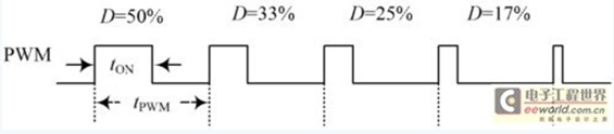
Figure 1 PWM waveform
2 backlight implementation hardware implementation
The S3C2440[4] is a 16/32-bit RISC embedded microprocessor based on the ARM920T core from Samsung. There are five 16-bit timers inside, of which the first four timers (TOUT0~TOUT3) have PWM function, the fifth timer (TOUT4) is an internal timer without output pins, and the timer TOUT0 has A dead zone generator, typically used for high current device control.
The PWM signal can be generated in hardware or it can be generated by software. Because the PWM signal is generated by software, the peripheral circuit is simple, the pulse width precision is high, and the control is flexible. Therefore, the program uses the timer TOUT1 of S3C2440 to generate the PWM signal periodically. By changing the duty cycle of the output pulse signal of the TOUT1 port GPB1, the backlight is controlled. switch. The LCD backlight adjustment circuit is shown in Figure 2.

Figure 2 LCD backlight adjustment circuit diagram
In Figure 2, the ZXLD1100 is an inductive PFM (Pulse Frequency Modulation) boost converter for driving white LEDs. When the LCD is operating normally, when the EN terminal of the ZXLD1100 is set high, the output will be driven by the LCD backlight. The required working voltage. Connect the port GPB1 of the S3C2440 to the enable terminal of the ZXLD1100, and enable the ZXLD1100 through the PWM signal to enable the LCD backlight to operate at a lower power.
In Figure 2, the button S1_KEY is used to increase the backlight brightness, and S2_KEY is used to lower the backlight brightness. The external interrupts used by S1_KEY and S2_KEY are EINT0 and EINT13 respectively. When the button is pressed, the system controls the duty cycle of the GPB1 output PWM signal according to the incoming button number, thereby completing the software control of the backlight of the device and realizing the backlight brightness. Adjustment.
3 backlight adjustment software design
The software part of the backlight adjustment is mainly the driver design. The device driver is a bridge between the hardware and the operating system kernel. It shields the hardware details of the application, and the application uses a unified system call interface to access the device. Linux systems divide devices into three basic types, namely character devices, block devices, and network devices. The backlight driver referred to herein is a character device driver. Linux is used as the embedded operating system, the kernel version is Linux 2.6.32, the root file system is Yaffs2, and the application program uses Busybox. The backlight driver's workflow block diagram is shown in Figure 3.
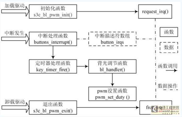
Figure 3 backlight driver workflow block diagram
(1) When the driver is loaded, the initialization function s3c_bl_pwm_init() is called. This function will call the request_irq() function to register the interrupt.
Request_irq() will operate the interrupt descriptor array button_irqs. The main function of the interrupt descriptor array is to record the key number and GPIO port corresponding to the interrupt number.
(2) When the interrupt arrives, the button number corresponding to the interrupt number is queried in the interrupt descriptor array button_irqs. Then call the interrupt handler to adjust the backlight of the device.
(3) When the driver is unloaded, the exit function s3c_bl_pwm_exit() is called. The function will call free_irq(), operate the interrupt descriptor array button_irqs, release the interrupt number used by the device and delete the corresponding interrupt handler.
3.1 backlight driver initialization and exit function
When the driver is loaded, the kernel calls the initialization function s3c_bl_pwm_init(). First initialize the LCD backlight brightness, set the button interrupt trigger mode, registration interrupt. Then initialize the timer and set the initial state of the button to lift (KEY_UP). Finally, misc_register() is used to register the hash device with the kernel, which is an abstraction of the character device. The definition of hybrid devices in backlighting is as follows:
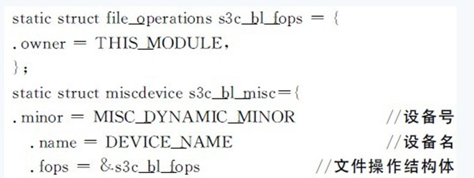
When the driver is unloaded, the kernel calls the exit function s3c_bl_pwm_exit(), logs off the interrupt and the hash device, and performs the opposite behavior of the initialization function.
3.2 Key interrupt and timer handler
When the button is pressed, a fast interrupt will occur, triggering the interrupt handler buttons_interrupt(). In the interrupt handler, when the initial state of the button is raised (KEY_UP), the button state is set to be indeterminate (KEY_DOWNX), and then the timer delay debounce is started, and the timer processing function is entered. Exit the interrupt handler if the current initial state of the button is not raised. In the timer handler, read the button GPIO port level and check if the button is still pressed. If the button is still pressed and the button state is undefined (KEY_DOWNX), the current button state is indicated as being pressed (KEY_DOWN). At the same time delay a relative debounce for a longer time, start a new timer, each time the timer expires, the query button is still pressed and the button state is pressed (KEY_DOWN), and if so, restart A new timer; if the query has not been pressed, the status of the button is raised, and the new button should be interrupted. Each time the logo button status is pressed (KEY _DOWN), the backlight adjustment function bl_handler() should be called to adjust the backlight brightness according to the incoming button number. The flow of the key interrupt and timer processing functions is shown in Figure 4.
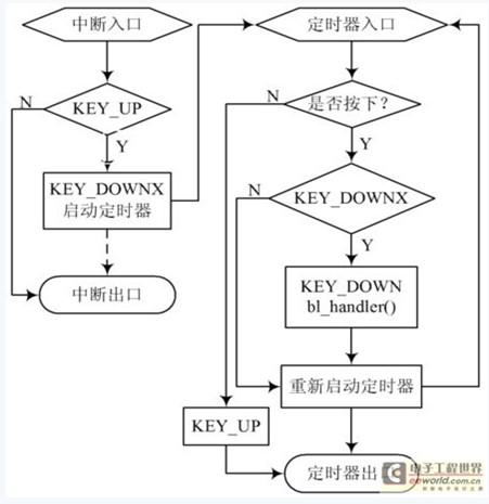
Figure 4 Flow chart of key interrupt and timer processing functions
3.3 PWM setting function
There are two registers TCNTBn and TCMPBn in the PWM timer, which are the timer count buffer register and the timer compare buffer register [10]. TCNTBn is used to set the PWM output pulse frequency, and the value of TCMPBn is used to set the PWM signal duty cycle. Therefore, by writing different TCMPBn values, the output signal duty cycle can be adjusted to achieve the PWM function, that is, to reduce the pulse width of the PWM, the TCMPBn value should be reduced, and instead the PWM pulse width is increased. To increase TCMPBn. If an inverter is used, the result of increasing and decreasing is that the double buffering feature allows the timer to override the value of TCMPBn while it is operating.
The PWM setting function pwm_set_duty() rewrites the value of TCMPBn according to the incoming parameters, and the output waveform can be changed in real time. The PWM setting function sets the PWM function of the timer TOUT1 port GPB1. The operation steps are as follows:
(1) enabling system