The living standards are constantly improving, and the comfort of travel has been paid more and more attention. As a result, the taxi industry has discovered a good opportunity for the Nuggets. However, there are always sales disputes that plague the development of the industry. The bottom line is to improve the taxi meter.
This article refers to the address: http://
The taxi meter based on the single-chip system design introduced today is a single-chip control unit with a single-chip microcomputer. It uses sensitive Hall-switching devices with powerful functions, reliable performance, simple circuit and low cost, plus optimized The program makes it highly intelligent.
1 system hardware design
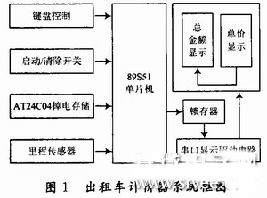
The taxi meter system is based on the AT89S51 single-chip microcomputer and consists of a button circuit, an AT24C02 power-down storage circuit, a mileage calculation circuit, and a digital tube display circuit. With the flexible programming design of the MCU and the rich I/O port, and the accuracy of its control, it can not only realize the basic mileage pricing adjustment, clock display, but also realize the extended function to a large extent, and at the same time facilitate the system in the future. Upgrade. Figure 1 shows the block diagram of the meter system.
1.1 Mileage calculation, pricing circuit design
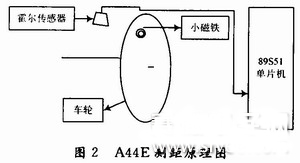
The signal detected by the Hall sensor A44E mounted on the wheel is sent to the single chip microcomputer, processed and calculated, and sent to the display unit, thus completing the mileage calculation. The detection principle is shown in Figure 2. The P3.2 port is used as the input end of the signal. The internal interrupt 0 is used internally. Each turn of the wheel (the circumference of the wheel is 1 m), the Hall switch detects and outputs a signal, causing The interrupt of the single-chip microcomputer counts the pulse. When the count reaches 1 000 times, that is, 1 km, the single-chip microcomputer controls the amount to be automatically increased. The calculation formula is:
Current unit price × km = amount
1.2 Data display circuit design
The design requires a unit price (2 digits), a distance (2 digits), a total amount (3 digits) display output, plus an additional extended clock display (including hourly and minute display), using LCD liquid crystal segment code display, at the distance screen The data cannot be seen from 1 m away, and the requirements are not met, and the contrast is not satisfactory during the day, so the split screen display of the 6-digit LED digital tube is used.
The design uses a timer/counter to send an interrupt request signal to the host every 0.1 s, and uses the parallel interface circuit to complete the real-time display function of the clock. At the same time, the dynamic scanning circuit is used to complete the display of the taxi price and the current accumulated price. When the taxi does not go, press S1 to realize the split screen display of the data; when the car is walking, only the total amount and the unit price display are displayed. When the destination arrives, when the customer requests to view the total mileage, You can press S1 to switch to the mileage and unit price display for customers to inquire.
1.3 AT24C02 power-down storage circuit design
This design advantage lies in its simplicity and efficiency of processing. The function of the storage circuit is to store the currently set unit price information when the power is turned off. The memory circuit is shown in Figure 3. It is designed by Atmel's 2 KB serial electrically erasable and programmable memory chip AT24C02. The transmission method is I2C bus.
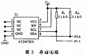
General address input terminal A0, A1, A2, write protection WP connected to Vcc or GND; SCL, SDA connected to pull-up resistor (the value of the pull-up resistor can be referred to the relevant data sheet selection, usually 5 ~ 10kΩ resistor can be selected, in the design The selected resistor is 5.1kΩ) and then connected to the ordinary I/O port of the microcontroller, which can realize the operation of the AT24C02. The pull-up resistor is used to reduce the static power consumption of the AT24C02.
1.4 Start and clear circuit
In the system circuit, a start/clear button is designed to act as a switch to initiate a mileage count or clear the mileage count. The button switch is connected to an interrupt request line of the microcomputer system, and when the switch is pressed once, it is used as a taxi start interrupt request; when the button is pressed once again, it is used as the system's log clear interrupt processing.
1.5 button circuit design
The circuit uses a total of four buttons, namely S1, S2, S3, S4, its function is: S1 is the split screen display switch button; S2 is the function setting button; S3 is '+' / day and night switch button; S4 is '- '/ Waiting for the switch midway.
2 system software design
2.1 main program module
The main program flow chart is shown in Figure 4. In the main program module, the initialization of each interface chip, the initialization of the taxi price and unit price, the design of the interrupt vector, and the opening and loop waiting are required. In addition, the main program module also needs to set the start/clear flag register, the mileage register and the price register, and initialize them. Then, the main program will perform different operations such as startup, clearing, metering, and pricing according to the contents of each flag register.
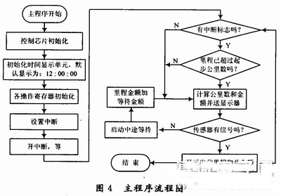
When S1 is pressed, the pricing is started and the mileage is calculated and judged based on the contents of the mileage register. If it has been exceeded, the current accumulated price is calculated based on the mileage value, the unit price per kilometer and the starting price, and the result is stored in the price register, and then the time and the current accumulated price are displayed on the display circuit.
When the destination is reached, since the Hall switch does not send a pulse signal, the pricing is stopped, and the current amount and the corresponding unit price are displayed. The next time the meter is started, the system automatically clears the display and re-initializes the process.
2.2 Timed Interrupt Service Program
In the timer interrupt service routine, an interrupt is generated every 100 ms. When 10 interrupts are generated, it is 1 s, the data is sent to the corresponding display buffer unit, and the display subroutine is called to display in real time.
2.3 Mileage Count Interrupt Service Program
Whenever the Hall sensor outputs a low level signal, the MCU interrupts once. When the mileage counter counts the mileage pulse for 1 000 times, the program accumulates the current total amount, so that the microcomputer enters the mileage count interrupt service routine. In this program, the accumulation of the current mileage and total amount needs to be completed, and the result is stored in the mileage and total registers.
2.4 Waiting for interrupt service routine
When the Hall switch has no output signal in the counting state, the on-chip T1 timer is activated. When the timing reaches 10 min, the current amount is added to the unit price waiting in the middle, and every 10 min is automatically added in the middle. Unit price. When the middle of the waiting is over, it automatically switches to the normal pricing.
2.5 Start/Clear the Tax Interrupt Service Program
When the system has a start/clear interrupt request, the first interrupt can be set as the start interrupt, the second interrupt is the clear interrupt, and the contents of the flag register are set to "1" or clear "0" in the interrupt service routine. ". Among them, when the flag is "1", it indicates that the interrupt is a startup interrupt; when it is "0", it indicates that it is a clear interrupt.
2.6 Displaying the subroutine service program
Since it is split screen display data, four display subroutines are used, namely: hourly minute and second display subroutine (HMS_DIS), amount unit price display subroutine (CP_DIS), distance unit price display subroutine (DP_DIS) and unit price adjustment. Subprogram (PA_DIS).
2.7 keyboard service program
The keyboard adopts the way of query and is placed in the main program. When no button is pressed, the MCU loops the main program. Once the right button is pressed, it will turn to the corresponding subroutine for processing, and the process ends and then returns.
3 Conclusion
The system has the characteristics of strong function, reliable performance, simple circuit and low cost. It is completely attributed to the use of single-chip microcomputer as the core control component of the taxi meter, using sensitive Hall sensor device as detection, plus optimized program. The level of intelligence is further improved, which solves the shortcomings of inaccurate pricing and short service life. It is a very practical solution.
Highlighting waterproof IP68 LED STRIP,with uniqute technology,can be used underwater.High quality smd 2835 led which is epistar chips packed.This led strip light is very safe since the input voltage is only 24vdc, so it can be avoid of electric shock even if it goes wrong operation.All the pcb and electronic parts are totally covered by special PU glue which is anti-uv for 5 years.The led strip is very energy saving,for example,60leds per meter is only 6w/m..High-flexibility,easy to be installed.These led strips are CE,ROHS,FCC certificated.
Smd2835 Led Strip Light,Led Strip Lights For Home,Pool Light Fixture,Outdoor Pool Lighting
Guangdong Kamtat Lighting Technology Joint Stock Co., Ltd. , http://www.ip68ledstrip.com