**Introduction and Classification of Hall Sensors**
Hall sensors, also known as Hall effect sensors, are magnetic field sensors that operate based on the Hall effect. They are widely used for measuring various physical quantities such as current, voltage, and position. These sensors are known for their high accuracy, good linearity, and reliability, making them essential in industrial automation, detection systems, and information processing applications.
Hall sensors can be broadly categorized into two types: linear and switch type. Linear Hall sensors are further divided into open-loop and closed-loop (zero-flux) configurations. Open-loop sensors are typically used for measuring AC or DC currents and voltages, while closed-loop sensors offer higher accuracy by balancing the magnetic flux through feedback mechanisms. These devices usually consist of a Hall element, a linear amplifier, and a follower circuit.
Switch-type Hall sensors, on the other hand, are designed to provide digital outputs. They include components like a Hall element, differential amplifier, voltage regulator, Schmitt trigger, and output stage. These sensors are commonly used in proximity sensing, speed detection, and position monitoring.
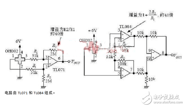
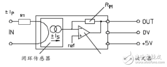
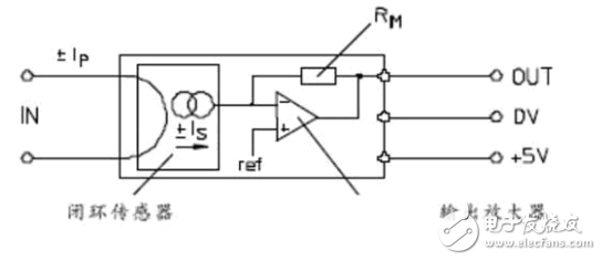
**1. Hall Sensor Circuit Diagrams (Signal Amplifier Circuit)**
Below is a diagram showing the signal amplifier circuit of a Hall sensor. This circuit is essential for amplifying the weak Hall voltage generated by the sensor, making it suitable for further processing and measurement.
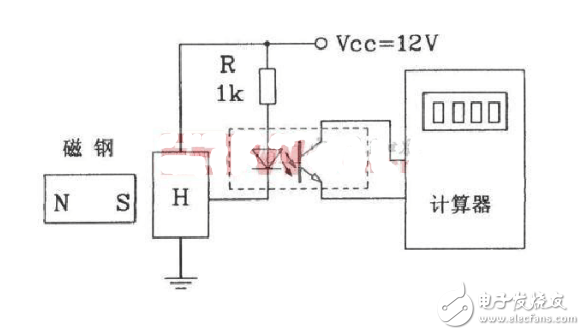
**2. Hall Sensor Circuit (Counter Circuit Using Hall Proximity Switches)**
This circuit uses Hall proximity switches to count the number of times a magnet passes by. It incorporates an optocoupler for isolation and an 8-bit counter to track the pulses. Each time the magnet approaches the switch, the counter increments, enabling precise counting applications.
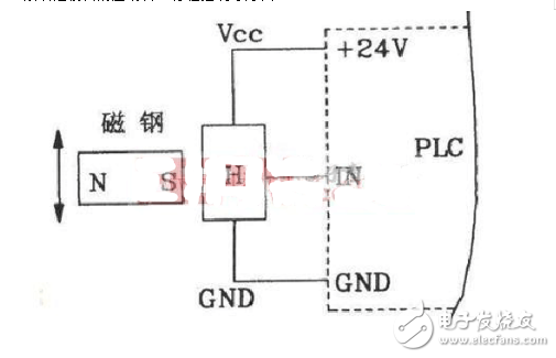
**3. Hall Sensor Circuit (CNC Machine Tool PLC Circuit)**
This Hall sensor-based circuit is often used in CNC machine tools and programmable logic controllers (PLCs). It offers high precision, up to 0.02mm, and is ideal for high-speed operations, complex cutting, and stroke control.
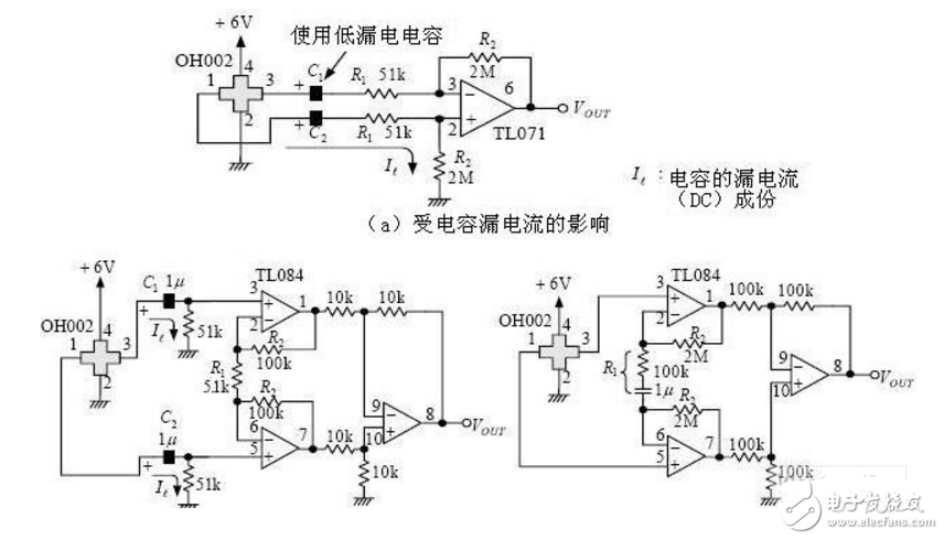
**4. Hall Sensor Amplifier Circuit Diagram**
Here is another example of a Hall sensor amplifier circuit, which enhances the output signal from the Hall element for more accurate measurements.
**5. Hall Current and Voltage Sensor Schematics**
Hall sensors are also used in current and voltage measurement systems. There are two main types: magnetic balance and direct detection.
**Magnetic Balance Hall Voltage Sensor:**
The primary voltage is converted into a current using a resistor, and the Hall sensor balances the magnetic flux created by the primary and secondary currents. This allows the secondary current to accurately reflect the primary voltage.
**Magnetic Balance Hall Current Sensor:**
Similar to the voltage sensor, this configuration balances the magnetic flux between the primary and secondary currents, ensuring accurate current measurement.
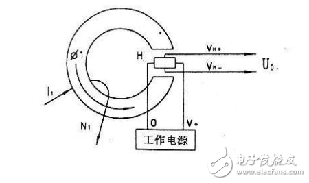
**Direct Detection Hall Current Sensor:**
In this design, the Hall element directly detects the magnetic field caused by the current. The output voltage is proportional to the current being measured, with standard values of 50mV or 100mV at rated current.
These circuits demonstrate the versatility and importance of Hall sensors in modern electronic and industrial systems. Whether for precise measurement, control, or sensing, Hall sensors continue to play a critical role in many technological applications.
Road Stake Actuator,Used Linear Actuators,Linear Screw Actuator,Electric Lift Mechanism
Kunshan Zeitech Mechanical & Electrical Technology Co., Ltd , https://www.zeithe.com