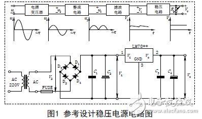
The operation of any electronic device is closely tied to a DC power supply. Transistors and integrated circuits require a stable DC voltage to function properly. There are two primary methods for providing DC power: dry batteries and regulated power supplies. Dry batteries offer the advantages of stable output voltage and portability, but they have limited capacity and a short lifespan. On the other hand, a DC stabilized power supply can convert 220V AC into a steady DC output. It typically consists of four main components: a transformer, rectifier, filter, and voltage regulator. A reference circuit is shown in Figure 1.
The output voltage of a regulated power supply is usually determined based on the specific needs of the equipment. Some devices may require multiple different voltages simultaneously. In such cases, a separate regulated power supply can adjust the output voltage within a certain range. When a large adjustment range is needed, it can be divided into several gear positions. To achieve this, the alternating current must first be converted to a suitable amplitude using a power transformer, followed by rectification. If necessary, the secondary coil of the transformer often uses two or more transformers to handle 220V ± 10% AC input and convert it into low-voltage AC to meet the power requirements. The following principles should be followed:
1. Ensure a reliable and stable output at 220V ± 15%. The DC voltage after transformation, rectification, and filtering is generally determined as follows:
- Minimize the input and output voltage difference for integrated voltage regulators.
- Account for the forward voltage drop across two diodes in a bridge rectifier.
- Leave some margin to prevent excessive heat dissipation or instability at low voltages.
2. The transformer must retain more than 20% current margin to ensure reliable performance under varying loads.
2. Rectification
Rectification converts sinusoidal AC into pulsating DC using the unidirectional conduction property of diodes. Common rectifier configurations include half-wave, full-wave, and bridge rectification. Most power supplies use a bridge rectifier, which consists of four diodes. Each diode must meet two key parameters:
- The current must be sufficient to support the load. Since the diodes in a bridge rectifier operate alternately, each one only carries half the load current.
- The reverse breakdown voltage must exceed the peak voltage of the transformer’s output.
3. Filtering
Filtering smooths out the pulsating DC by reducing ripple. Capacitors or inductors are commonly used, with large electrolytic capacitors being the most common choice. In the circuit, C2 and C4 are low-frequency filter capacitors, while C1 and C3 are high-frequency capacitors used to eliminate self-excitation and stabilize the output. The capacitance and voltage rating of these capacitors are calculated based on the circuit requirements and grid fluctuations. Low-frequency capacitors typically range from hundreds to thousands of microfarads, while high-frequency capacitors are between 0.01μF and 0.33μF. Key considerations include:
- The capacitor's withstand voltage must be higher than the maximum voltage in the circuit.
- For the filter capacitor after regulation, values in the hundreds of microfarads are typically used.
- The capacitance can also be calculated based on the load current: C2 ≥ (IL / 50mA) × 100μF.
4. Voltage Regulation
The DC voltage after rectification and filtering is still unstable, containing ripples and fluctuating with changes in AC input and load. This instability can cause malfunction in connected devices. To address this, a voltage stabilizing circuit is added. There are two main types: discrete component-based regulators and integrated voltage regulators. Among them, series regulators are widely used due to their simplicity and effectiveness.
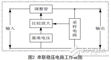
(1) Series Regulator Circuit
A typical series regulator circuit includes a sampling circuit, reference voltage circuit, comparator amplifier, and an adjustment circuit. The block diagram is shown in Figure 2.
(2) Integrated Voltage Regulator
With the advancement of integrated circuit technology, voltage regulators are now available as three-terminal ICs, known as three-terminal voltage regulators. These offer advantages like safety, reliability, ease of use, and cost-effectiveness. They come in four categories based on output type:
1. Fixed positive voltage regulators (e.g., 7800 series like 7805 for +5V).
2. Fixed negative voltage regulators (e.g., 7900 series).
3. Adjustable positive voltage regulators (e.g., LM117, LM217, LM317).
4. Adjustable negative voltage regulators (e.g., LM137, LM237, LM337).
5. Safety and Heat Dissipation
A DC stabilized power supply should always include a fuse and a heat sink. The fuse protects the circuit by automatically cutting off power in case of a short circuit or overload. The heat sink ensures that the temperature of the integrated voltage regulator remains within safe limits.
Power Cable,Hv Power Cable,Xlpe Insulated Cable,Pvc Insulated Cable
HENAN QIFAN ELECTRIC CO., LTD. , https://www.hnqifancable.com