Intelligent traffic lights represent the future of traffic management and flow control. They are designed to more effectively regulate, adjust, and guide traffic, thereby improving efficiency and ensuring road safety. This system integrates the strengths of existing traffic light technologies while addressing their limitations. It is specifically tailored for domestic driving conditions, which involve random vehicle movements and various influencing factors. The design combines video capture, image processing, and control modules. At its core, an FPGA is used for high-speed video acquisition, while a DSP processor performs real-time image calculations. Vehicle data is extracted through image algorithms, and a fuzzy logic approach is applied for intelligent control.
**1. System Design Overview**
The system consists of three main components: the video acquisition module, the image analysis module, and the control module. It is designed to be efficient, intelligent, and practical. As shown in Figure 1, the video acquisition module is built around an FPGA, which leverages its high-speed parallel processing capabilities to control CMOS image sensors and efficiently store and transmit image data.
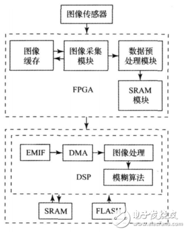
*Figure 1: System structure*
The image processing module is based on a DSP, which uses its powerful computing resources and multi-bus architecture to process images and analyze traffic flow in real time. The control module includes a software algorithm and a DSP port, allowing it to interface with different driving circuits to manage various types of traffic signals.
**2. Video Capture Module**
The video acquisition module, as shown in Figure 2, is built using an FPGA, with peripheral extensions such as a CMOS image sensor and SDRAM memory.
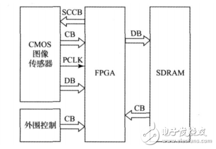
*Figure 2: Video capture module structure*
The OV7660 CMOS image sensor’s control and data signal terminals are directly connected to the FPGA, which uses nearly 400 state machines to accurately handle timing commands. To ensure smooth operation across modules, the system buffers image data frame by frame, storing both the current and previous frames in SDRAM. While the current frame is being written, the previous frame is read.
The DSP accesses the FPGA as external SRAM via the EMIF interface, reading image frames through a timer-controlled DMA. This streamlined signal path maximizes the advantages of FPGA timing control, and by optimizing the caching strategy, it improves the stability of data transmission, laying a solid foundation for subsequent image analysis.
**3. Image Processing Module**
Traffic flow detection is a key component of intelligent transportation systems. Using video images for this purpose offers cost-effectiveness, simplicity, adaptability, and scalability. The primary goal of the image processing module is to separate the foreground from the background, identifying moving vehicles against a static background.
Traditional methods like optical flow, interframe difference, and background subtraction are used for moving target detection. Among these, the background difference method is widely adopted. It subtracts the background reference frame from the current frame, then applies thresholding to binarize the difference image and detect moving objects.
The success of background subtraction largely depends on the quality of the background model. Since the background can change due to lighting variations, the system uses an adaptive update algorithm. It starts with a mean-based initial background image, builds a background model using the Kalman filter principle, and applies the OTSU algorithm for image binarization.
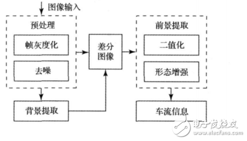
*Figure 3: Video image processing flow*
**3.1 Frame Graying**
The DSP reads 16-bit RGB565 color image data from dual-port RAM. To speed up processing while preserving most details, the brightness information is extracted and converted into YUV format. The brightness equation is:
Y = 0.299 × R + 0.587 × G + 0.114 × B
The result is shown in Figure 4(b).
**3.2 Noise Reduction**
The original image captured by the camera often contains salt-and-pepper noise and white noise. Salt-and-pepper noise comes from sensors or transmission channels, while white noise is random Gaussian interference. To improve subsequent processing results, noise must be reduced, though some image quality may be lost. A balance must be struck between noise reduction effectiveness and processing speed.
The system uses a 3×3 sliding window median filter, which effectively reduces noise while preserving edges. Although not the fastest method, it has minimal impact on real-time performance. The 3×3 pixel sequence is divided into three groups, and the minimum, median, and maximum values are calculated. The final result is the median of the three values. The effect is shown in Figure 4(c).
The mirror wire are used for car recorder and car backing radar.
What does our product include?
| 1 | JST wire harness |
| FH-----0.5mm ZH-----1.5mm | |
| SH-----1.0mm PH-----2.0mm | |
| GH-----1.25mm VH-----3.96mm | |
| EH/XH-----2.5/2.54mm | |
| 2 | Molex wire harness |
| PicoBlade-----1.25mm PicoClasp-----1.0mm | |
| PiciLock------1.0/1.5mm Minifit Jr-----4.2mm | |
| MicoBlade-----2.0mm MicoClasp-----2.0mm | |
| MicoLock-----1.25/2.0mm | |
| 3 | IDC flat ribbon cable |
| Contact material----Copper alloy | |
| Test voltage------500V AC | |
| Current rating-----1A | |
| Cable Technical Data: | |
| Contact Material----Tin plated copper | |
| Isolationswiderstand-->1000MΩ | |
| Insulation Resistance-->1000MΩ | |
| Temperature range----- -40℃.....105℃ | |
| UL Typ---------UL2651,28AWG |
Mirror Wire,Turn Signal Mirror Harness,Mirror Wire Harness,10 Pin Connector Wire Harness
Dongguan YAC Electric Co,. LTD. , https://www.yacentercn.com