The MCS-51 is a widely used 40-pin dual in-line package (DIP) microcontroller that serves as a foundational component in many embedded systems. Below is a detailed breakdown of its pin configuration and functions:
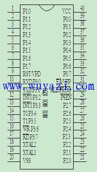
- **P0.0 ~ P0.7**: These are the 8-bit bidirectional I/O lines of Port 0. When used as an address/data bus, they can also be configured for external memory expansion.
- **P1.0 ~ P1.7**: These are 8-bit general-purpose I/O pins that are fully bidirectional. They can be used for input or output operations.
- **P2.0 ~ P2.7**: These are 8-bit bidirectional I/O lines of Port 2, often used for higher-order address bits when expanding memory.
- **P3.0 ~ P3.7**: These are 8-bit bidirectional I/O lines with additional secondary functions, such as serial communication, timer inputs, and interrupts.
- **ALE (Address Latch Enable)**: This signal is used to latch the lower 8 bits of the address from the P0 port during memory access. It also provides a fixed frequency clock signal (1/6 of the oscillator frequency), which can be used externally.
- **PSEN (Program Store Enable)**: This active-low signal is used to read from external program memory (ROM).
- **EA (External Access)**: This signal determines whether the microcontroller uses internal or external program memory. A low level enables external memory, while a high level selects internal memory.
- **RST (Reset)**: When this pin is held high for at least two machine cycles, it resets the microcontroller and initializes the system.
- **XTAL1 and XTAL2**: These are the crystal oscillator input and output pins. They are used to connect an external quartz crystal or an external clock source.
- **VSS**: Ground terminal.
- **VCC**: +5V power supply.
Understanding these pins is essential for designing circuits and programming the MCS-51 microcontroller. Each pin has a specific role, and proper configuration ensures the system operates correctly. Additionally, the second function of P3 lines allows for more advanced features like serial communication, external interrupts, and timer controls. By referring to the pinout diagram and matching it with your circuit design, you can easily identify and connect each pin for optimal performance.
645/675 Series Push Wire Connectors
PCB Connector,Fanuc Board Connectors,Single Plug Hole Connectors,Good Use Wire Connectors,pcb push wire connector,pcb cable connector
Jiangmen Krealux Electrical Appliances Co.,Ltd. , https://www.krealux-online.com