Power semiconductors have a heavy responsibility in the electronics world, and their thermal management is critical to the reliability and longevity of component operation. To this end, TDK Group has introduced a series of EPCOS negative temperature coefficient (NTC) and positive temperature coefficient (PTC) thermistors to help customers reliably monitor the temperature of semiconductor components. Power semiconductors generate heat losses ranging from a few watts up to several kilowatts. For thermal management of power semiconductors, the power semiconductor components are designed to be mounted on a block of heat sinks to facilitate more efficient heat dissipation. The heat sink conductivity unit is K/W. The smaller the value, the greater the heat dissipation. If a certain semiconductor is known to have the greatest heat dissipation, the highest expected ambient temperature, and then consider the relevant contact thermal resistance, the desired type of heat sink can be determined. If passive heat dissipation is generated by convection alone, the temperature limit will be reached in a relatively short period of time. However, if the chip area is small and the power consumption is large, it is impossible to ensure sufficient cooling by this method. In addition, the size of the heat sink will make it difficult for the device to achieve a compact structure. The only remedy is to use air-cooled fans or water-cooled heat exchange systems, and they need to be operated without additional adjustment. In most applications, including power units and converters used in computers and notebooks, power consumption is tied to the load. To improve the energy balance and prevent the generation of unnecessary noise, we recommend that active heat dissipation be performed only after reaching a certain temperature limit in most applications. EPCOS thermistors are available in numerous models and are suitable for a wide range of applications, making them ideal for detecting temperature limits. In terms of the basic technology of thermistors, there are significant differences between the positive temperature coefficient (PTC) and the negative temperature coefficient (NTC) thermistors, and the resistance temperature curves of the two are essentially different (see Figure 1). Figure 1: Resistance characteristics of positive temperature coefficient (PTC) and negative temperature coefficient (NTC) thermistors
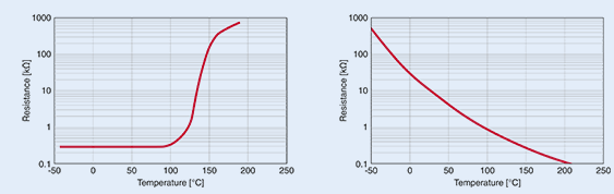
Above a certain temperature, the resistance of a positive temperature coefficient (PTC) thermistor (left) rises sharply, so it is suitable as a temperature limit sensor. The resistance of the negative temperature coefficient (NTC) thermistor is linear, so it is suitable for temperature measurement.
Positive temperature coefficient (PTC) sensors provide reliable temperature monitoring Positive temperature coefficient (PTC) Thermistors have a steep curve and are therefore suitable for monitoring temperature limits and start the fan after reaching a certain set temperature. The positive temperature coefficient (PTC) temperature characteristic has the additional advantage that a positive temperature coefficient (PTC) thermistor can be connected in series, so that as a temperature sensor is used, it can easily monitor multiple hot zones as long as If a series positive temperature coefficient (PTC) sensor exceeds a certain temperature limit, the circuit will enter a high-impedance state. This principle also applies to notebooks. To facilitate monitoring of the host processor, the graphics processor and other heating elements should be patched PTCs. Positive temperature coefficient (PTC) sensors can also be used for thermal monitoring of three-phase motor windings. To this end, TDK Group has introduced a series of special models that can be assembled according to the respective requirements and can be easily integrated with the windings. Figure 2 shows a positive temperature coefficient (PTC) sensor for temperature limit monitoring. Figure 2: EPCOS Positive Temperature Coefficient (PTC) Sensor
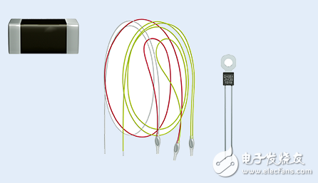
From left to right: SMT positive temperature coefficient (PTC) sensor mounted on printed circuit board, positive temperature coefficient (PTC) sensor integrated with motor winding, positive temperature coefficient (PTC) sensor with Terminal Block installed on heat sink
Switching principle: Recording temperature limits Figure 3 shows a simple circuit consisting of two series positive temperature coefficient (PTC) sensors. TR1 forms a voltage divider with two positive temperature coefficient (PTC) sensors. This voltage divider provides the non-inverting input of the op amp while the op amp acts as a comparator. As for TR1, when set, its maximum value should be approximately equal to twice the room temperature resistance. The TR1 can also be fine-tuned accordingly. In the cold state, a potential appears at the non-inverting input, and this potential has a higher negative potential than the potential at the inverting input. This means that there is a negative voltage at the comparator output. If one or two positive temperature coefficient (PTC) sensors reach the corresponding temperature limit, the potential of the voltage divider will change, and the comparator will switch and send a positive output signal, which in turn turns off the transistor. Figure 3: Circuit for monitoring temperature using a positive temperature coefficient (PTC) sensor
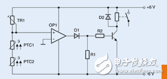
Circuits for monitoring two hotspots: For example, a fan will automatically turn on when the temperature limit is exceeded.
One sensor detects two temperature-correcting temperature coefficient (PTC) thermistors. Negative temperature coefficient (NTC) thermistors can also be used for temperature monitoring. In applications requiring linear characteristics, negative temperature coefficient (NTC) thermistors are mainly used. We will show how reliable the negative temperature coefficient (NTC) thermistor performs temperature monitoring by the following example. In this example, a negative temperature coefficient (NTC) thermistor will be used to monitor the end of high performance audio. Two temperatures. To ensure the smallest possible case size, eight output transistors in the TO-3 package are mounted together with the emitter resistor on a combined cooling fan unit. The four independent heat sinks are arranged in a point-symmetrical manner. Install two power transistors on each heat sink (see Figure 4). Figure 4: Fan/cooler included
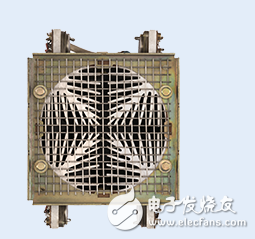
In this design, all four heat sinks must be thermally tested.
Special attention must be paid to the thermal monitoring of the output transistors because such output transistors are mounted on four heat sinks and the four heat sinks are insulated and insulated from each other, ensuring that each heat sink is monitored individually. The reason for this is that, even if the size of the transistor is large enough, the tolerance will cause uneven load distribution. Thermal monitoring must be performed in both stages: When one or more heat sinks reach 85°C, the fan must be automatically turned on, and when the temperature reaches 100°C, load shedding must be performed. With a temperature sensor, this dual function can be achieved at the same time. Negative temperature coefficient (NTC) sensors of the EPCOS K45 or M703 series have emerged. Figure 5: EPCOS Negative Temperature Coefficient (NTC) Sensor
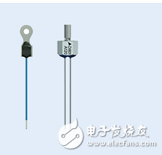
Thanks to lugs (left) or bolts (right), these EPCOS Negative Temperature Coefficient (NTC) sensors provide a good thermal contact for the heat sink.
The 4 heatsinks (B57045K0103K000) use EPCOS K45 series thermistors with R25 of 10 kΩ. According to the data table, the RT/R25 ratio is 0.089928 at 85°C, which results in a resistance of about 900Ω. At 100°C, the resulting resistance is approximately 500Ω. For double temperature detection, a circuit with two comparators is required. The complete circuit actually completed is shown in Figure 6. Figure 6: Double temperature protection at the end of audio
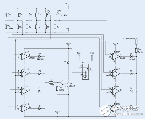
With this circuit, 4 heat sinks can be thermally monitored. When the temperature is higher than 85°C, the fan will be activated. In unfavorable environmental conditions, the temperature can even reach 100 °C, and then load rejection. To accomplish this operation, the DC voltage protection circuit will receive a positive signal, causing the relay to trip.
The reference value of the 2 switching thresholds will be set by 2 trimmers, namely R7 and R8 (2.2 kΩ respectively). As mentioned above, two trimmers will produce a resistance of either 900Ω or 550Ω, respectively. As for the 8 required comparators (U1A-U1D and U2A-U2D), the economical LM324 amplifier is used. A test lasting several hours in full-load jumper mode shows that the fan can reliably turn on at 85°C. Because the system has a relatively low thermal period, there is no need to use a commonly used hysteretic comparator circuit. To test the insulation in a high-temperature environment, we tested the end phase immediately after the fan was disconnected, and the detected safe disconnect temperature was 103°C. By fine-tuning R8, this value can be accurately adjusted to 100°C. Because EPCOS NTC and PTC sensors are available in various models with different features, design and fixing options, they can be reliably implemented in almost all possible applications. Thermal management work.
2.54mm (0.1") Pitch Female Headers
Overview
The most commonly seen female headers are 2.54mm (0.1") single or double row female/socket headers. These female headers together with its male counterpart are used in connecting Arduino boards and shields together. 2.54mm pitch female sockets/headers are low-profile connectors designed for signal and low power PC board connections when space is at a premium. They have the perfect height for clearing the USB-B connector and great for stacking multiple shields.
Since 2.54mm pitch female header is commonly used in a lot of applications, Scondar offers numerous options for this type of female header. Orientation can either be SMT or THM, single, dual or triple row. Antenk offers 2.54mm pitch female headers in either vertical or right-angle orientation. The pins and blades are also available in various sizes, counts, amperages, and plating.
The 2.54mm can accommodate a maximum current of 3A, with a 30 to 22 AWG wire size, and up to 40-positions. Antenk offers these female headers in high quality and affordable China-quoted price that snuggly fits with the pins of a male header and acts as a receptacle.
If you can not find the items you interest from above items, welcome to contact us, and you will always get fully responsive from us.
Applications of 2.54mm Pitch Female Headers
Electronics:
LED applications
Arduino boards
Arduino Pro
Arduino Mega
Solar applications
Weighing systems
Appliances:
Air conditioner
Refrigerator
Microwave oven
Washing machine
Water heater
Shower toilet
Washer/Dryer
Stove
Automotive, Heavy Duty Military and Marine
For densely packed equipment requiring weight reduction and downsizing and for tough and harsh conditions.
Vehicle infotainment
Computer peripherals
Battery Connections
Battery connections rely on the ability of the current to pass reliable and solid current. This prevents overheating in the circuit and voltage drop.
Rechargeable battery packs
Battery balancers
Battery eliminator circuits
Medical Diagnostic and Monitoring equipment
Heart monitors
Telecoms
Datacoms
Mount Type: Through-hole vs Surface Mount
At one side of this female header is a series of pins which can either be mounted and soldered directly onto the surface of the PCB (SMT) or placed into drilled holes on the PCB (THM).
Through-Hole (Poke-In)
Best used for high-reliability products that require stronger connections between layers.Aerospace and military products are most likely to require this type of mounting as these products experience extreme accelerations, collisions, or high temperatures.
Useful in test and prototyping applications that sometimes require manual adjustments and replacements.
2.54mm, 1-row vertical female header, 2.54mm, 2-row vertical female header, 2.54mm, 3-row vertical female header, 2.54mm, 1-row right-angle female header and 2.54mm, 2-row right-angle female header, 2.54mm U-
Shaped Female header, 2.54mm U-Shaped Dual Row Female header are examples of Antenk products with through-hole mount type.
Surface-Mount
The most common electronic hardware requirements are SMT.
Essential in PCB design and manufacturing, having improved the quality and performance of PCBs overall.
Cost of processing and handling is reduced.
SMT components can be mounted on both side of the board.
Ability to fit a high number of small components on a PCB has allowed for much denser, higher performing, and smaller PCBs.
2.54mm, 2-row right-angle female header and 2.54mm, 1-row right-angle female header are Antenk`s featured SMT female headers.
Orientation/Pin-Type: Vertical (Straight), Right-Angle and U-Shaped
2.54mm pitch female headers may be further classified into pin orientation as well, such as vertical or straight female header, right-angle female header or U-shaped female header.
Vertical or Straight Female Header Orientation
One side of the series of pins is connected to PCB board in which the pins can be at a right-angle to the PCB surface (usually called "straight" or [vertical") or..
Right-Angle Female Header Orientation
Parallel to the board's surface (referred to as "right-angle" pins).
U-Shaped Female Header Orientation
U-shaped orientation is characterized by the shape of the pins at one side of the header, forming a letter [U". It is often chosen for applications where repeat mating cycles are not required as it can also be used and soldered directly to both PCB's.
Each of these pin-types have different applications that fit with their specific configuration.
Single, Dual or Multiple Number of Rows
For a 2.54mm straight or vertical female header, the standard number of rows that Antenk offers ranges from 1 to 2 rows. However, customization can be available if 3, 4 or n number of rows is needed by the customer. Also, the number of contacts for the single row is about 2-40 pins while for dual row, the number contacts may vary from 2-80 pins.
Pin Material
The pins of the connector attached to the board have been designed with copper alloy. With customer`s demand the pins can be made gold plated.
Custom 2.54mm Pitch Female Headers
Customizable 2.54 mm pitch female headers are also available, making your manufacturing process way faster as the pins are already inserted in the headers, insulator height is made at the right size and the accurate pin length you require is followed.
Parts are made using semi-automated manufacturing processes that ensure both precision and delicacy in handling the headers before packaging on tape and reel.
Tape and Reel Packaging for SMT Components
Antenk's SMT headers are offered with customizable mating pin lengths, in which each series has multiple number of of circuits, summing up to a thousand individual part number combinations per connector series.
The tape and reel carrier strip ensures that the headers are packaged within accurately sized cavities for its height, width and depth, securing the headers from the environment and maintaining consistent position during transportation.
Antenk also offer a range of custom Tape and reel carrier strip packaging cavities.
Pcb Header Connector,2.54Mm Female Pin Header,2.54Mm Pcb Header,2.54Mm Pcb Connector,0.1" Pitch Female Headers,2.54mm SMT Female Pin Header, THT 2.54mm Female Pin Header
ShenZhen Antenk Electronics Co,Ltd , https://www.antenkwire.com