Micro-electromechanical (MEMS) gyros are widely used in aviation, automotive automation and consumer electronics, and are mainly classified into line vibrating gyros and rotating vibrating gyros according to the vibration structure. As the cost and power consumption of MEMS gyros are continuously reduced and the volume and weight are gradually reduced, new requirements such as high precision and high sampling frequency are also proposed for the digitalization scheme. In order for MEMS gyros to work at high frequencies, digital circuits need to have high sampling frequencies. Currently, the digitization of MEMS gyros is mainly through the use of embedded field programmable gate display (FPGA), digital signal processor (DSP) chips or A combination of them is implemented.
Finally, the MEMS gyro is used for test verification on the platform, so that the signal demodulation and control of the gyro can be realized on the PC side, and the actual use process is more convenient than the general FPGA or DSP. High-speed transmission of PC and capture card through PCIe (PCIexpress) bus, the maximum control delay is less than 10μs.
1. Computer low-speed optimization design for real-time control systemReal-time performance As a key indicator of the gyro measurement and control system, this section will focus on designing and optimizing the low latency and stability of the control system. The first part of low latency optimization mainly includes hardware optimization and software optimization. Hardware optimization needs to consider the type of high-speed bus and the transmission control method of high-speed bus; while software optimization mainly involves optimization of operating system driver level and optimization of control algorithm. The second part of the stability optimization is to let the computer real-time control system stably generate the output signal. In actual engineering, the system's control of the gyro equipment is prevented from being affected by the interruption delay and the transmission delay fluctuation.
1.1, low-latency optimization of data transmission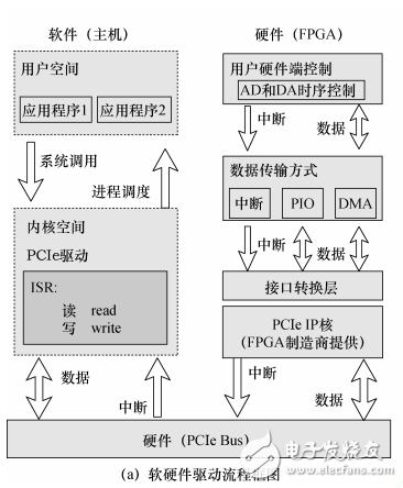
Figure 1 Low-latency optimization scheme for real-time measurement and control platform
Figure 1a shows the hardware and software framework and data flow of the real-time measurement and control platform. After the hardware interrupt is issued, the data collected by the AD needs to pass through the interface conversion layer, the PCIeIP core of the FPGA, the PCIe bus, etc. to reach the computer IO memory space. After the memory address mapping is completed, the user program can read data from the memory for data processing. In actual multi-threaded data transfers, additional delays are generated, as shown in Figure 1b, with interrupt latency, thread latency, and thread context switch latency. The interrupt latency is defined as the time difference between the execution of the computer hardware interrupt and the execution of the first instruction in the Interrupt Service Routine (ISR), which is mainly related to the kernel architecture, CPU frequency and load. Due to scheduling between threads, the kernel needs preparation time for saving and restoring the thread context, getting or releasing semaphores, and so on. The thread delay is defined as the time difference from the thread signal that is waiting to wake up in the ISR to the time the thread executes the first instruction. The thread context switch time is the time difference between the execution of the first instruction of a thread and the execution of the first instruction of the second thread.
Closed Pod Electric Vape 3.5ml Pod
Closed Pod Electric Vape 3.5Ml Pod,2 In 1 Vape,Smoking Succedaneum E-Cigarette,Vaporizer E-Cigarette
KENNEDE ELECTRONICS MFG CO.,LTD. , https://www.axavape.com