The transmitter is one of the important devices for wireless communication, and is widely used in the fields of broadcast television, mobile communication, marine transportation and national defense. Automatic control technology is playing an increasingly important role in the field of wireless communication transmission, and the digitization of transmission equipment is gradually becoming mature. However, high-power short-wave transmitters have more frequent switching frequency and shorter scrambling time than medium-wave, FM, and TV transmitters; they cannot achieve solid-state solidification, reduce reliability, and have high failure rates; Wide, it is difficult to ensure stable operation at any frequency in the whole frequency band; in addition, there is no interface standard to regulate the real-time control of the high-power short-wave launcher microcomputer, which brings difficulties to the automation of high-power short-wave launch pad. The automatic tuning technique of short-wave transmitters is generated in this environment.
The design of the automatic tuning system is based on FPGA and AVR microcontroller, the tuning object is a short-wave transmitter with a power of 150kW and a transmission frequency range of 3.9 26.1MHz. The system structure is shown in Figure 1:
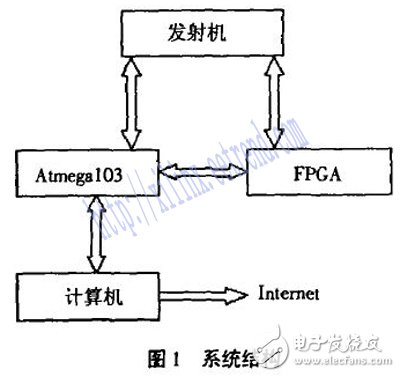
FPGA is the abbreviation of Field Program-Device Gate Array. It is a new generation of automatic tuning control unit. It uses VHDL language for field programming. Its features are: I/O resources are rich, and the operation speed is fast (ns Level), high integration, good stability, a large number of LUTs and triggers, and so on.
In view of these characteristics, the system intends to use a combination of a single-chip microcomputer and a field programmable gate array (FPGA). The FPGA mainly completes the human-machine interface, the logic design for measuring the working frequency of the transmitter and adjusting the position of the component, and the single-chip microcomputer completes tasks such as upper computer communication, component position data acquisition, and storage system parameters. The system logic part design is mainly completed in the system design. Figure 2 shows the logical structure of the system.
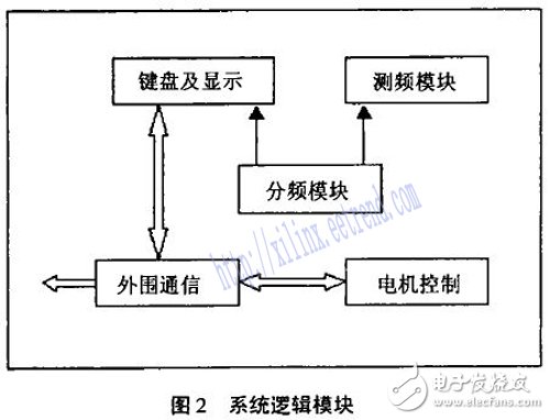
The design of each logic module in the system is mainly done in VHDL hardware description language.
3 System Function Overview 3.1 Automatic Tuning Transmitter auto-tuning refers to the operation of adjusting each tuning element to a position corresponding to the frequency according to the operating frequency of the current transmitter during the tuning process. The on/off of each power unit of the short wave transmitter is realized by the on and off of the corresponding contactor in the distribution box. The signal that controls the on and off of the contactor is generated by the tuning logic box. The automatic tuning control box is used to realize the tuning control of the mechanical positioning of the high frequency loop component of the transmitter during frequency change. In order to achieve the purpose of tuning, the automatic tuning system needs to complete the following tasks:
(1) In order to realize the remote monitoring of the launch pad by the staff, the automatic tuning system needs to be connected to the online computer;
(2) The system needs to set various parameters, and needs a simple human-machine interface, mainly keyboard and LED Display;
(3) Storage and recall of system parameters;
(4) Determination of the actual operating frequency of the transmitter;
(5) Acquisition of tuning element position information;
(6) Control the position of the motor adjustment component.
The operator first creates each working channel through the control panel, and each working channel stores the adjustable component position value corresponding to the working frequency and frequency of the transmitter. Once you have created your working channel, you can enter normal tuning. Select a working channel, and press the function key, the system will issue an interrupt request to the MCU. The FPGA takes the frequency value corresponding to the channel and the position information of the 8 tuning components from the EEPROM of the MCU, and the actual position of the 8 tuning components collected by the MCU. Information is also passed to the FPGA for comparison with preset values, which are used to control the motor. The tuning system also has an automatic frequency measurement module, which is used to determine the actual operating frequency of the transmitter. When the value is equal to the predetermined value, the system automatically presets the component position value.
The main valid parameters of the system are: working channel, working frequency, and position value of the component being tuned.
There are 8 adjusted components in the whole machine:
1 way – high-precision loop capacitor, used as tuning (rough adjustment, fine adjustment) at this level;
2 way - high end cavity short circuit board, only for coarse adjustment:
3 way - high-order state tuning capacitor, as a coarse adjustment, fine call;
4 way - high end tuning capacitor, as a coarse call;
5 way - high-end load transfer capacitor, as a coarse adjustment, fine call:
6-way - high-end load-carrying coil, as a rough call;
7 way - as a backup;
8 way - high pre-level tuning inductor, as a coarse call.
The system has "manual", "semi-automatic", "automatic", three kinds of tuning methods.
The "automatic" tuning mode is mainly used in the normal working process of the system; the premise that the "preset" can be adopted is that the adjusted components are in place, the mechanical hysteresis and electrical of the system are within the allowable range; the "semi-automatic" mode is the auxiliary mode. It overcomes the shortcomings of the automatic mode in which individual frequencies cannot be adjusted to the optimum state.
(1) Manual mode The "manual" mode is a manual tuning mode on the operation panel for initial tuning and creation of channels, operating frequencies and position values ​​of corresponding components to be tuned. The fine adjustment and initial coarse adjustment of all the adjusted components are completed by manual control; “manual†can be used to obtain the positioning value, and the channel initialization and working frequency setting can be manually performed through the enable button on the panel and the 0-9 numeric keypad. The position of the adjustable components is set, and the set value can be saved each time a channel is set.
Advantage
1. Utra Thin and Light weight, Cabinet weight only 19KG and 86mm thickness.
2. In direct sunlight, the outdoor LED display can be high-definition and high-brightness, high refresh rate, high contrast
3. Can withstand high and low temperature, can be used in extremely harsh environment
4. Modular design, Front and Rear maintenance system available, Separate and exchangeable power and data unit can be easily removed for easy maintenance
5. Outdoor IP65 is waterproof, dustproof and corrosion proof, ensures smooth and reliable operation under variable and extreme weather conditions.
* Nova MSD 300 sending card and Nova mrv328 receiving card
* Cabinet size:640x1920mm
* Kinglight/Nationstar LED Lamp, Refresh rate:1920-3840hz
* High brightness up to 2000cd/sq.m, even in the sunlight conditions can see clear, but low power consumption to save the electric power cost.
* High debugging brightness and no damage to gray scale, achieving the debugging technology for nice image.
* Passed the TÃœV,FCC,ROHS,CE cetification.
Poster LED Display,Poster Led Display,Mirrior Led Display,Led Poster Display
Guangzhou Chengwen Photoelectric Technology co.,ltd , http://www.cwledpanel.com