Please continue reading, I will give you a few examples of buying lamps directly from Chinese dealers.
Case 1: There are 5 wall lights on the wall of our new restaurant. At first glance they are fine, but in reality it seems a bit crappy. I really want to replace them with better lights, but I have never found a suitable one. In addition, there is no reasonable way to add a master switch to these lights, so each lamp requires its own switch, which does reduce the range of choice.
I decided to try to build something for the future: a white plexiglass panel with LED strips on the back and brightness control through touch. My plan is to make a microcontroller-based touch controller from scratch, but I can't help but take shortcuts after discovering that the market's LED touch controllers cost less than $20.
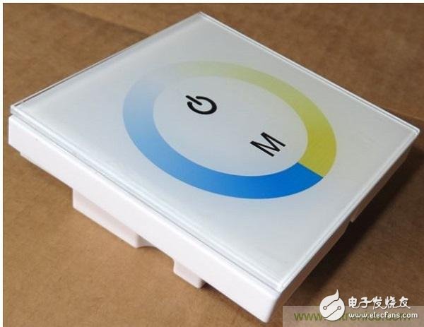
When I first conceived my design, I imagined alternately displaying cool white and warm white LED strips, and able to achieve a gradient between warm and cold, but I quickly denied the use of cool white strips (who Want to use a cool white light source in the restaurant?).
When I was looking for a touch dimmer in various types of single-channel and RGB models, I definitely chose a product that could change between cool white and warm white. It costs no more than a single channel product. I haven't tried it yet, but I'm sure there is no overlap in these two areas. If I really did a two-channel design, I wanted to be able to illuminate both at the same time.
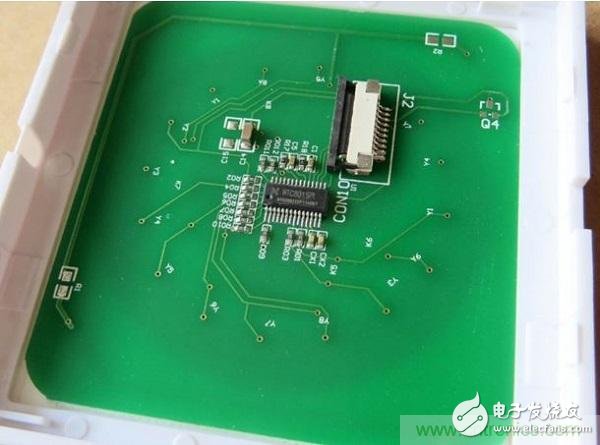
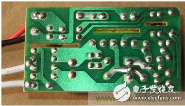
Touch the back of the panel PCB. I didn't recognize this IC, and the "W1C801SPI" written on the package could not find any information.
The motherboard's microcontroller or ASIC has been blurred, but its basic identity (perhaps a PIC) can be identified by a small number of traces.
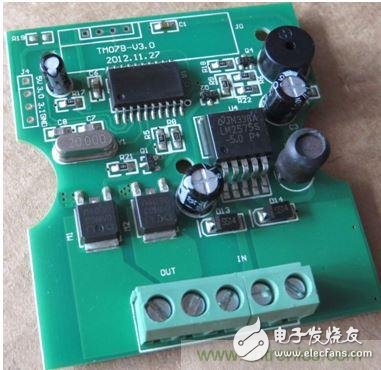
I am very surprised by the U4 5V 1A switch. To be sure, a 7805 can fully meet the current requirements! Otherwise, if the buzzer is too annoying, I will definitely melt it with a soldering iron.
In order for my plexiglass touchpad design to work properly, I also need a power supply. Here's what I paid for $4:
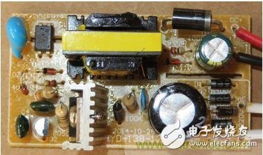
12V, 1.5A power supply, bought with a plastic case.
Power expert readers: What do you think? There are no outstanding advantages, because it is too bad for me, although the input capacitance is only 400V - not much for the 240V input. I think 450V devices are more common (12V output capacitors are best for 25V power supplies).
The welding surface of the power supply.
According to some circuit traces, I guess this is a simple flyback design. In fact, there is no obvious control chip at all, unless it is pretending to be a transistor or optocoupler. The gate of power transistor Q1 is connected to Q2 and IC1.
Case 2: My bathtub needs lighting. RGB lighting is best. why? I do not know. I guess because I can do it (the audio and video rack may need the same processing).
The first remote I bought used infrared:
Prices for these products range from $5 to $10, depending on the complexity of the remote.
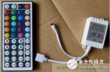
But I can't reject this stylish RF (433.92MHz) touch controller for $22:
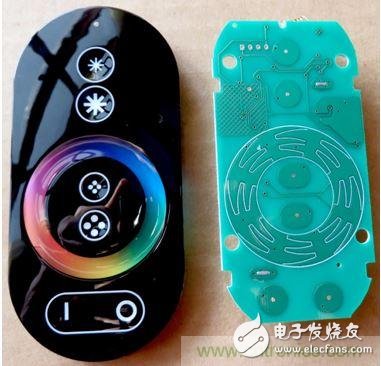
Top to bottom: Brightness, Chroma, Saturation (?), On/Off/Mode (Static or Dynamic).
After measurement, three AAA batteries have a quiescent current of 175μA, so if you are lucky, a battery can be used for one year.
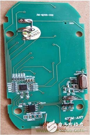
Q1 and Q2 may be voltage regulators.
U1 is Cypress's CapSense controller, U2 is an unknown microcontroller, and U3 is a radio frequency transmitter.

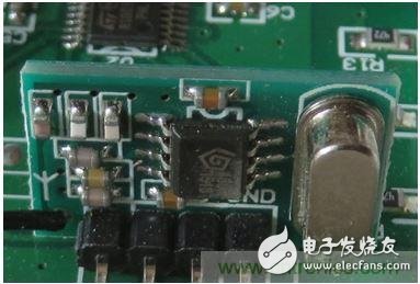
Receiver and LED driver module.
Written on the housing is 216W, which means 72W per channel, or 6A@12V. It is praised that MOSFETs have this processing capability, but in this case you may want to handle a total current of up to 18A by rewiring.
U2 may be a microcontroller from STMicroelectronics. Below is a clearer picture of the RF receiver:
Can you recognize this IC manufacturer?
I did a brief test of this RGB controller and used the built-in LED to monitor the output. This controller works a bit strange, when at least two LEDs are lit. Given that this remote control has what I call saturation control, this is understandable. All three LEDs are lit to mean that there is a certain amount of white light, ie <100% saturation. This is fine, but for some reason, the saturation control only responds when only one LED is lit. Also, when I change the color, the output reverts to 100% saturation.
Ok, this may be good enough. But I also want to try infrared remote control, in case infrared can provide better color control. Stay tuned for my follow-up report! Source: Electronic Technology Design.
Usb Wireless Charger,Best Wireless Charger,Wireless Charger Price,Wireless Mobile Charger
wzc , https://www.dg-wzc.com