This paper introduces the design of an embedded service robot somatosensory remote controller with ARM as the core. In hardware, the remote control adopts STM32F103C8T6 with ARM Cortex-M3 core as the core processor, and adopts ST company's iNEMO inertial navigation module to identify the hand posture, and also has LCD display module, wireless transceiver module and power module; software On the other hand, the embedded operating system μC/OS-II is used to realize multi-task scheduling and peripheral device management. The remote control has the advantages of high stability, high real-time performance, high reliability and low error rate.
This article refers to the address: http://
introduction
As the integration of various high-tech development achievements, service robots need to communicate human-computer interaction in a humanized, simple and natural way for the purpose of service. The traditional push-button remote control obviously cannot meet this design requirement. At present, somatosensory devices are developing rapidly, and various types of devices based on somatosensory control are emerging one after another. Somatosensory control is achieved through changes in limb movements
Control, human-computer interaction based on somatosensory devices has become a hot topic in current research.
Common wireless remote control technology is nothing more than infrared remote control technology and radio remote control technology. The advantage of the infrared remote control technology is that the bandwidth is large, but the strong directivity is required, the transmission distance is short, the penetration ability is poor, and the power consumption is high; compared with the radio remote control technology, the directionality, the anti-interference ability and the penetration ability are strong. The transmission distance is long and the power consumption is low. Therefore, radio remote control technology is more suitable for smart home, consumer electronics and robot control.
This article uses STM32F103C8T6 as the main controller, using iNEMO inertial navigation module, nRF24L01 wireless module and 12864 liquid crystal display module. The embedded inductive remote controller has the advantages of small size, simple operation, high reliability and strong expandability. It can better meet the requirements of reliable remote control for service robots and has great application and promotion value.
1 system function requirements and overall architecture
1.1 Basic functional requirements
1 has the ability to accurately send the corresponding control commands in real time. The content of the instruction is determined according to the hand posture.
2 has the ability to receive the robot body backhaul data packets. The data packet is parsed according to the received data packet to determine whether the control command received by the body is correct.
3 Display capability of current command and current state information of the robot. On the one hand, the sent control command is displayed on the LCD screen; on the other hand, according to the data packet returned by the robot body, the state of the robot is analyzed and displayed on the LCD screen.
4 with battery power detection and low voltage alarm function. The remaining power is displayed on the LCD screen in real time. When the battery is low, an alarm is given by the buzzer.
1.2 System overall plan and structure
The basic principle of the iNEMO inertial navigation module is shown in Figure 1. The MEMS sensor and the main control chip STM32F103RET7 provide dynamic and static direction and inertial measurement functions. Integrated dual-axis roll-pitch gyroscope (LPR430AL), single-axis yaw gyroscope (LY330ALH), 6-axis geomagnetic measurement module (LSM303DLH), pressure sensor (LPS001DL) and temperature sensor (STLM75) 5 STMicroelectronics The sensor runs an AHRS attitude angle calculation system to achieve real-time measurement of the attitude angle.
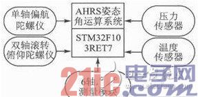
The basic principle of iNEMO inertial navigation module
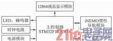
The remote controller adopts ARM's ARM controller STM32F103C8T6 with Cortex-M3 core as the main controller, adopts ST company's iNEMO inertial navigation module for hand posture detection, adopts nRF24L01 wireless module to realize command transmission and data reception, adopting 12864 The liquid crystal display module displays the current control command, the current state of the robot and the remaining power, and uses LEDs and buzzers to implement the prompt and alarm functions. The μC/OS-II real-time embedded operating system on the remote control software enables real-time kernel, task management, time management, communication and synchronization, and memory management. The overall architecture of the system is shown in Figure 2.
2 hardware circuit design
2.1 main control module circuit
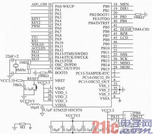
The main controller STM32F103C8T6 chip, operating frequency up to 72 MHz, built-in 64 KB Flash and 20 KB SRAM, with a wealth of peripherals and ultra-low power, fully meet the design requirements. The circuit diagram of the main control module is shown in Figure 3. Refer to the STMF10xxx hardware development entry document released by ST. This part includes the design of external clock circuit, analog power input, power supply filtering, and download emulation port.
2.2 Power Module Circuit
The remote control is powered by a 8.4 V lithium battery. It uses a TL750M05C regulator to provide 5 V. The REG1117-3.3 regulator is used to provide 3.3 V to the system. STM32F1 03C8T6 power supply is divided into analog power supply and digital power supply. In order to ensure its normal operation, the two power supplies are isolated and designed to achieve single point common ground between the analog ground and the digital ground through a 0Ω resistor. In order to monitor the lithium battery power supply voltage, the battery voltage is filtered by the resistor divider and the RC filter circuit as the STM32F103C8T6 sampling input.
2.3 Wireless communication module and display module circuit
The wireless communication module uses the 2.4 GHz band RF chip nRF24L01 as the wireless data transceiver chip, working in the 2.4 to 2.5 GHz ISM band, and the output power and communication channel can be configured through the program. The nRF24L01 consumes low power and operates at -6 dBm with a current of only 9 mA. At reception, the operating current is only 12.3 mA. A variety of low-power modes of operation (power-down mode and idle mode) make energy-efficient design easier. The nRF24L01 communicates with the control chip using the SPI bus.
12864 liquid crystal display module, which can display Chinese characters and graphics, built-in 8192 Chinese characters (16×1 6 dot matrix), 128 characters (8×16 dot matrix) and 64×256 dot matrix display RAM (GDRAM) with parallel data Transmission mode and serial data transmission mode, wherein serial data transmission mode only uses CS, SID, SCK three communication pins, and parallel data transmission mode saves I/O pins of single-chip microcomputer. This article uses serial transmission mode. design.
3 software system design
The software system design of the somatosensory remote control is based on the real-time embedded operating system μC/OS-II. With the multi-task management of the μC/OS-II core and excellent real-time performance, the software system design is greatly simplified and the system response can be guaranteed. real-time.
3.1 Task assignment and implementation
In the process of mission planning, the entire system task is divided by hierarchical and modular ideas. First of all, we must have a clear understanding of the overall control tasks of the system, the specific tasks are listed in Table 1.

In addition to the OSTaskStat and OSTaskIdle tasks in Table 1, the other eight tasks are created by the user. Among them: App_TaskStart is the starting task, the first task established after the system runs, its role is to create all events and other tasks for initializing the system clock and the underlying device; App_TaskAD task to monitor the change of battery voltage, when the voltage is lower than the set value When the Low Battery is used, the buzzer alarm will be activated; the App_TaskAHRS task continuously receives the iNEMO inertial navigation module data through the DMA, and then passes to the USART1 receiving buffer to obtain the hand posture information in real time; App_TaskCmd is converted into the robot motion instruction according to the hand posture information. Then, according to the established communication protocol, the instruction data packet is sent out through the nRF24L01 wireless module; the App_TaskData task receives the motion state information packet returned by the robot body through the nRF24L01 wireless module after each transmission of the instruction data packet; the App_TaskLCD task realizes the motion instruction and the robot The movement state, battery power, and real-time clock are displayed on the 12864 liquid crystal display module; the App_TaskLED_B task indicates whether the main control chip on the remote controller and the iNEMO inertial navigation module, the remote controller and the robot communicate normally through the LED, when the battery power is too low, through The buzzer is used to alarm; the App_TaskClock task gets the real-time clock of the DS1302 and is sent to the App_TaskLCD task via the message mailbox App_LCDClockMbox for real-time display.
3.2 Inter-task communication design
Tasks and interrupt service subroutines can communicate with other tasks through event control blocks. Common communication methods include semaphores, mailboxes, and message queues. At the same time, event and flag synchronization is achieved through event flags. The operating system has created a total of 8 message mailboxes and 1 event flag:
OS_EVENT *App_AHRSMbox
OS_EVENT *App_CommandMbox
OS_EVENT *App_DataMbox
OS_EVENT *App_ADMbox
OS_EVENT *App_LCDCmdMbox
OS_EVENT *App_LCDDataMbox
OS_EVENT *App_LCDADMbox
OS_EVENT *App_LCDClockMbox
OS_FLAG_GRP *App_GreenLEDFlag
Among them, App_GreenLEDFlag includes 3 flag bits:
#define Flg_GreenLED 0x0001
#define Flg-BlueLED 0x0002
#define Flg_Buzzer 0x0004
3.3 Software System Flow Chart Design
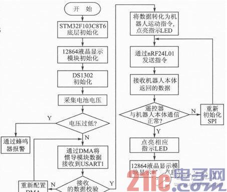
The software system flow chart is shown in Figure 4. After the power-on remote controller is initialized by power-on, the battery voltage is first collected, and then the collected power value is sent to the 12864 liquid crystal display module through the mailbox *App_ADMbox for display. If the power is too low, the flag bit Flg_Buzzer is set, that is, by the bee. The alarm is given an alarm. Moreover, the data of the iNEMO inertial navigation module is received by the DMA to the USART1 to determine whether the check digit is correct. If not, the DMA is reconfigured to re-receive the data; if correct, the received data is converted into a control command, and the nRF24L01 wireless The module is sent to the robot. At the same time, the command is sent to the App_TaskLCD task via the mailbox *App-LCDCmdMbox, and the currently sent command is displayed in the 12864 liquid crystal display module, and the corresponding LED is lit by setting Flg_GreenLED to indicate that the communication between the STM32F103C8T6 and the iNEMO module is normal; after the robot body receives the command The data packet will be returned to the remote controller. If the data error flag received by the remote controller is not set, the remote controller communicates with the robot body normally. The status information of the robot is sent to the App_Tas kLCD task via the mailbox *App_LCDDataMbox, at 12864 LCD. The movement state of the robot body is displayed on the display module, and the corresponding LED is lit by setting Flg_BlueLED to indicate that the remote controller communicates with the robot body normally. The App_TaskClock task sends the current time information to the App_TaskLCD task via the mailbox *App_LCDClockMbox and displays it.
The somatosensory remote control software system development environment is IAR EWARM5.4, the μC/OS-II version is V2.86, the STM32F103C8T6 debugging tool is J-Link emulator, and the STM32F103C8T6 firmware library version is V2.0.3.
3.4 Design of communication scheme between remote controller and robot body
This design adopts a strict "one question and one answer" form, that is, each time an instruction is sent, the robot body needs to return a frame of data packets. After the remote controller sends an instruction, it waits for the data packet returned by the robot body, and can only continue to send the instruction packet after obtaining the data packet returned by the robot body. If the robot body receives an error command (a command that has been verified incorrectly), the communication error flag is set, and the data packet is uploaded. At the same time, the robot body alarms to set the robot speed to 0, and then the lower computer clears the serial port DMA within 1 s. Re-receive the command. If the communication error flag is set in the data packet received by the remote controller, reconfigure the nRF24L01 wireless module and resend the command.
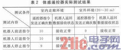
4 performance test
The embedded robotic remote controller described in this paper was tested accordingly. The test environment was indoor corridor environment and outdoor environment. The test results are listed in Table 2. The test results show that in the indoor corridor environment, the correct rate of sending and receiving instructions is above 95%; in the outdoor environment, due to various interferences in the environment, and the distance is 20-30 m, the correct rate is above 90%. Because the underlying software of the remote control has a certain fault tolerance, more than 90% of the correct rate fully meets the requirements.
Conclusion
This paper discusses the design and implementation of the embedded service robot somatosensory remote controller based on STM32F103C8T6, and introduces the specific hardware circuit and software system in detail. After a large number of experiments, the proprioceptive remote control has the advantages of simple operation, strong operability, reliable communication, high stability and humanization, and has achieved good results in the practical application of laboratory service robots.
- STM32 microcontroller Chinese official website
- STM32 microcontroller official development tools
- STM32 microcontroller reference design
What kind of Metal Enclosed Switchgear is the medium voltage switch cabinet? It has good insulation performance for other equipment except medium voltage switch. It can avoid electric arc burning through power equipment and ensure the safety of power use. At the same time, it also avoids the expansion of fault range of medium voltage switch when using electricity. The medium voltage switch cabinet is composed of cabinet and circuit breaker, which has the functions of overhead incoming and outgoing lines, cable incoming and outgoing lines, bus connection, etc. The cabinet body is composed of shell, electrical components (including insulating parts), various mechanisms, secondary terminals and wiring.
Medium Voltage Motor Drive Solutions
8Pt Low Voltage Switch Cabinets,Low Voltage Switch Cabinet,Electric Motor Switchgear,Innovative Switchgear Solutions
Shandong Shunkai electrical equipment co., LTD. , https://www.chinasdsk.com