0 Preface
A constant current source is a power source capable of supplying a constant current to a load, also referred to as a steady current source or a current source. At present, the application of digitally controlled constant current sources has become more and more widely used with the development of electronic technology. In the high-tech fields such as electronic measuring instruments, lasers, sensing technology, superconductivity, and modern communications, constant current sources are widely used. And the development prospects are relatively good. At the same time, it is not limited to this. At present, the industrial demand urgently needed to be solved is to digitize the analog signal collected in industrial production and use it as the constant current of the control signal, and participate in the control of the next level of production.
1 System structure and principle
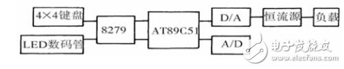
Transformer rectification, MCU control part, D/A and A/D conversion circuit, power supply part, display or keyboard interface circuit, constant current source circuit, etc. The digital constant current source is composed of the above parts. The system can also realize human-machine communication, which is mainly realized by LED digital tube and keypad. The LED digital tube displays the current value and some corresponding functions, while the keypad can realize the artificial control of the constant current source output. When there is no state under the control of the keypad, the input state of the user will be displayed, and when it is A/D sampling control, the main control part includes: analog-to-digital conversion chip, keyboard display interface chip, single chip microcomputer, driver chip, 8 Digits and bricks, etc. The core control chip adopts AT89C51 general-purpose single-chip microcomputer, which is the core control chip of the small control system which is preferred because of its complete functions, stable performance and low cost. Using A/D sampling processing to the D/A output, communication between the keyboard and the circuit can be performed, while 8279 manages the keyboard and circuit, so that the burden on the processor is reduced, and the mouth line and time of the microcontroller are excessively displayed by the display circuit and the keyboard. The problem of occupation can also lead to an ending. The overall block diagram of the system (Figure 1).
2 system hardware circuit design
2.1 Power supply and transformer rectifier
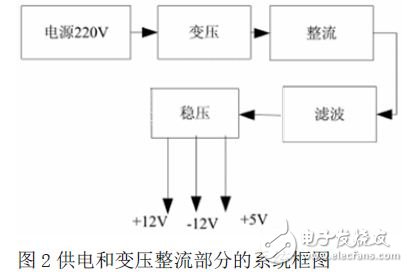
The power supply part mainly provides power for the D/A conversion chip and the numerical control part, and also serves as the main power supply for the regulated output circuit. Output 50hz, 200-240v AC, through the transformer rectification, transformation, filtering, get +12v, +5v, -12v, the voltage required by the three systems (as shown in Figure 2). To consider the voltage drop of the rectifier to select the filter capacitor, the grid fluctuation is 10%, choose 7912/7805/7812, because the 7812/7912 power is large, the load is heavy, you need to install a heat sink. So use 4700UF/16V as the filter capacitor. A filter is added to the output of the regulator to make the output current ripple ≤ 0.2ma.
2.2 Constant current source circuit simulation
The flow-controlled constant current source and the voltage-controlled constant current source are two control forms of the constant current source. The constant current source in the form of voltage control is introduced in this paper. The current range of 4-20ma, that is, the output current of 4-20ma, the control voltage The change can make the current change, but once the input voltage is determined, the output current will be constant, and the system can provide a constant current determined by the input voltage, mainly in the range of load resistance changes. Simulate the constant current source circuit characteristic curve (as shown in Figure 3).
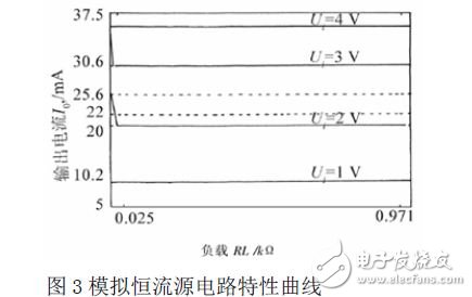
When the load resistance of this voltage-controlled constant current source circuit is between 29-10008Ω, we can see that the linearity with the input voltage changes is relatively good, and the change of the output current with the load resistance is very small.
2.3 Principle of keyboard display circuit
The connection circuit diagram of the keyboard display circuit and the single chip microcomputer can complete the corresponding operations on the display and the keyboard only by reading and writing. When the keyboard is pressed, the keyboard display interface chip will send an interrupt request to the MCU through the external interrupt of the MCU, and the MCU determines whether to perform the next task after making the judgment.
2.4 Principle of A/D Sampling Circuit
The A/D converter sampling input and the connection circuit diagram of the MCU, single sampling input, when the sampling is finished, the interrupt request will be issued in the way of the external interrupt of the MCU, and the MCU interrupt processing is required. At this time, the MCU should be on the A/D. The input data of the converter is judged and processed for the next control operation.
3 circuit analysis and testing
3.1 Test methods
External 220v AC power supply, digital multimeter, low frequency millivoltmeter, test to prepare the above instruments. Specific test methods (as shown in Figure 4). In the figure, the sampling resistance is RS and the load resistance is RL.
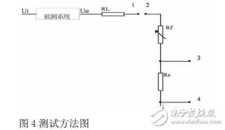
The values ​​at both ends of 1 and 2 are measured as measured current values ​​using a multimeter, and the values ​​at both ends of 3 and 4 are measured as low-output millivoltmeters as output ripple voltage values. In order to compare the error between the true value and the measured value, we selected eight values ​​of 20-2000ma for comparison. The error calculation formula is:

In the formula, the measured value is I2, and the displayed value is I1.
3.2 Test results
The error between the set value and the measured value is RL=8Ω when the load resistance is changed ten times, the set value is I3, and C1=(I2-I3)/I3 is the measurement error. Standard deviation of measurement error: RL=18Ω, S1=0.0036ma, S1=0.0031ma. The error between the set value and the displayed value is: RL=8Ω, C2=(I1-I3)/I3 is the measurement error, RL = 20 Ω, S2 = 0.0041 ma, S2 = 0.124 ma, which is the standard deviation of the measurement error. The percentage of error varies from 0.017 to 0.36.
4 control section
The system described in this paper is a two-way control of the output current, that is, there are two ways to control the signal source. One is to obtain the control signal by A/D sampling according to the needs of industrial applications, according to the multiple times in the assembly program. The data is measured, the fixed table is designed, and the control data is passed to the D/A output through the look-up table, so that the corresponding stable current generated by the constant current source unit is controlled. The manual input method is used to judge the ideal current value input by the user, and then according to the look-up table, the output of the control data is realized by D/A, thereby obtaining the current of the corresponding size, and the function can also allow the initial value user of the current. Make a preset. The above two control methods can not work at the same time. The program can realize automatic switching between two different control modes: automatic sampling and keyboard. When using the LED interactive display at the same time, the output current is displayed in real time for A/D sampling control; when the keyboard is controlled, the user's input status is displayed.
Refer to the relationship between the input voltage and the output current of the constant current source to tabulate, and some nonlinear problems can be corrected in the indicator process. In the process of tabulation, it is also necessary to write down the situation caused by the difference between the application of the A/D and the initial value of the keyboard input. Consider the initial value of the keyboard: If 10ma is the current input by the user, 1v is the corresponding control voltage, (00110010)2=(50)10 is the indirect corresponding 8-bit binary number, then (00110010)2 Is the corresponding value in the software table.
The A/D sampling control is basically the same as the keyboard mode, except that one more judgment is made on the sampled value.
5 software program design
First of all, including: 8297 initialization of the working state; automatic sampling control flag and initialization of the manual operation of the identification keyboard; interrupt initialization; initialization of some used registers, the entire system is initialized. It is prescribed that A/D sampling control is when F0=1, keyboard control when F0=0, initial writing initial setting state, here is the state of the keyboard, LED digital tube is displayed as P, also indicates keyboard state, start D/A Make the conversion. And wait for the keyboard to press and start looping. Some of them are added as follows: A/D sampling control display A; keyboard control state is P, and the display of the interactive button display is E.
6 Summary
The digital constant current source of this paper is designed based on single-chip microcomputer. It has the characteristics of real-time sampling control in industrial production and application. The application needs to use the constant current of the corresponding size as the signal of the lower level to realize the manual input and sampling automatic input of the keyboard. The dual control, and can freely switch the digital constant current source circuit under two control modes, the digital constant current source has good linearity and stable current output. In the dosing process of sewage treatment, the opening degree of the dosing valve can be controlled, and the effect of controlling the dosing amount can be achieved. After the determination, after adjusting the necessary software, some industrial application requirements can be completely obtained. Satisfy.
Circular Connectors are mostly designed for commercial signal and power applications.Common classification is material: all plastic connector and metal connector, collectively known as CPC connector.Generally, stable high temperature resistant thermoplastic materials are used, and the working temperature is - 40 ℃ - 105 ℃.Fast connection / disconnection with the help of thread, with active braking coupling function.Built in male and female pin protection device.
Circular Connectors
Circular Connector,Circular Connector Types,Circular Power Connector,Circular Electrical Connectors
Suzhou WeBest Electronics Technology Co.Ltd , https://www.webestet.com