This reference design shows how to develop a high performance, high voltage 2-wire or 3-wire 4–20mA current loop transmitter for industrial process control and smart sensors. In addition, error analysis test data, thermal characterization data, schematics, and analysis software are provided.
The 4–20mA Transmitter Design Calculation Sheet (XLSX) is now available for download.
introduction
The 4–20mA current loop is widely used as an analog communication interface in the industrial field, making it easy to transfer remote sensor data over a twisted pair to a programmable logic controller (PLC) in the control center. The interface is simple, can realize reliable transmission of long distance data, has good noise resistance, and has low implementation cost, and is very suitable for long-term industrial process control and remote automatic monitoring.
There is no doubt that industrial development, like all today's electronics applications, is demanding, requiring higher precision, lower power consumption, and reliable operation over the extended industrial temperature range of -40°C to +105°C. The security and system protection also requires support for the High Speed ​​Addressable Remote Sensor (HART®) protocol. All in all, these requirements make today's 4–20mA current loop design challenging.
This article describes how to develop 4–20mA current loop transmissions and perform performance analysis, and how to select components that meet stringent industrial requirements. Provide error analysis test data, thermal characterization data, schematics, and analysis software.
Working principle and key design parameters
We start with a reference design. Figure 1 shows a block diagram of a high-performance, low-power, 4–20mA current loop transmitter that dramatically reduces component count and provides the best price/performance ratio.
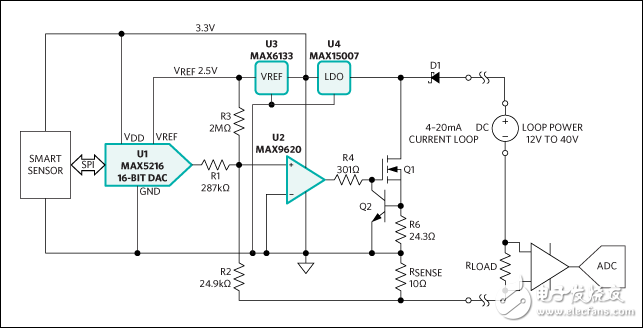
Figure 1. The 4–20mA loop-powered transmitter reference design consists of the MAX5216 16-bit DAC (U1), the MAX9620 operational amplifier (U2), the MAX6133 voltage reference (U3), and the MAX15007 LDO (U4).
The reference design features low power, high performance components with better than 0.01% accuracy at 25°C and over 0.05% accuracy over the entire temperature range, supporting the industry's most stringent 4–20mA current loop requirements. The design uses the MAX5216, low-power 16-bit DAC (U1); MAX9620, zero offset, rail-to-rail input and output (RRIO), high-performance operational amplifier (U2); MAX6133, voltage reference (U3); and MAX15007, 40V Low quiescent current LDO (U4).
The U3 voltage reference provides low noise, 5ppm/°C (max) low temperature drift and high 2.500V voltage for U1. The smart sensor microcontroller sends commands to U1 over a 3-wire SPI bus. The U1 output is divided and converted to a loop current by a Q1 power MOSFET, a 10Ω (±0.1%) current-sense resistor (RSENSE), and U2. The U1, U2, and U3 devices are powered by U4, which is powered directly by the loop. The Q2, BJT transistor and sense resistor (R6) form a current-limit circuit that limits the loop current to approximately 30mA, preventing runaway conditions and damaging the ADC on the PLC side. Schottky diodes (D1) protect the transmitter from reverse current damage.
Performance analysis
The reference design operates at low power consumption with a maximum current consumption of less than 200μA at +25°C and less than 300μA over the -40°C to +105°C temperature range. The U2 op amp has an input offset voltage of 25μV (max) over time and over the entire temperature range, making it ideal for high precision, high reliability systems. A 10Ω current-sense resistor allows for a lower loop supply voltage; a small resistor dissipates less power, allowing a small package to be used, further reducing transmitter size. For example, if there is only a 10Ω RSENSE and a 10Ω load, the maximum voltage drop across it is 600mV at 30mA. The U4 LDO only needs to be connected to a 4V supply voltage to provide a 3.3V output with a minimum loop voltage as low as 5V. However, if the PLC load is 250Ω, the minimum loop supply voltage must be 4V + 30mA &TImes; (10 + 250) Ω = 11.8V.
Note that in order to estimate the minimum loop supply voltage more accurately, the loop supply internal resistance must also be considered.
During the test, the output showed some noise at 10 Ω. Increasing the RSENSE resistor value will increase power consumption and minimum loop supply voltage, but also reduce loop noise. This overall balance can be controlled by the user.
The U2 op amp tracks the voltage drop across R2 and RSENSE, maintaining 0V at its two input nodes. The circuit satisfies the following relationship:
 (Formula 1)
 (Formula 2)
Where IOUT is the loop current I(R2) is the current through R2. I(R1) is the current through R1. I(R3) is the current through R3. In Equation 2, we assume that the IN+ and IN- input currents of U2 are zero. According to Equations 1 and 2, the 4 mA initial loop current is set by the I(R3) current and I(R1) is zero. and so:
 (Formula 3)
The current through R3 is equal to the U3 voltage reference output divided by R3. Equation 3 can be rewritten as:
 (Formula 4)
Based on the Namur NE43 recommendation for fault information sent over a 4–20 mA current loop, the measurement information ranged from 3.8 mA to 20.5 mA, allowing a slight linear overrange of process readings. In some cases, even larger fault ranges are required when additional fault conditions are defined, such as 3.2 mA to 24 mA. Therefore, select R2 = 24.9kΩ, IOUT_INIT = 3.2mA, and solve R3 from Equation 4 to get:
 (Formula 5)
The 1.945 MΩ resistor is costly and, more importantly, not suitable for automated production and is not conducive to field calibration. Therefore, a better approach is to use a standard 1% tolerance resistor to ensure the UmA DAC's 4mA offset current and 20mA full-scale current accuracy. In this case, a partial digital code needs to be calibrated to ensure the required accuracy. Therefore, I(R1) = VDAC/R1, where VDAC is the U1 DAC output voltage. The above formula is rewritten as:
 (Formula 6)
and
 (Formula 7)
Finally, Equation 1 can be rewritten as:
 (Equation 8)
The LTM series is designed to meet the needs of human-computer interaction in the market. Our engineers have developed 8-inch to 65-inch LCD touch monitors and touch all-in-ones to provide longer life, high picture quality, and a wide temperature range. It can be used for uninterrupted operation in rugged equipment in harsh environments (high and low temperature, humidity, salt spray and rain) and harsh conditions (high shock, high vibration, and fall). Support a variety of signal input interfaces, including VGA and Video, special requirements can increase DVI and HMI interfaces; support DC12V or AC220V power input, special requirements support DC 9 ~ 36V wide voltage input can be wall-mounted, folding / rotating bottom seat Embedded installation, open installation and other diversified installation methods to meet the various needs of customers. Specially designed folding base, adjustable for multiple angles; no shaking when touched; TFT digital true color LCD display mode to meet customer visual effects; hidden adjustment panel to make the frame more smooth and flat; touch screen can flexibly choose serial port, The USB port communicates with the host, using resistive screens, sonic screens, and infrared screens to meet customer environmental needs.
Desktop Monitor,4K Pc Monitor,Best Desktop Monitors,Desktop Computer Monitor
Shenzhen Hengstar Technology Co., Ltd. , https://www.angeltondal.com