Design and Implementation of GPRS Transmission Static Image System
Summary of design and implementation of GPRS transmission static image system: This paper introduces a software and hardware implementation scheme of GPRS wireless static image transmission system, focusing on the design of terminal mobile station and communication software for transmitting image data via Internet. In addition, two flow control methods used by the GPRS client for wireless network data transmission are also introduced.
Keywords: GPRS wireless network communication TCP / IP protocol image transmission
GPRS is a way to provide packet services in the GSM system. For the transition from 2G to 3G, GPRS is the most widely used technical solution that can solve the combination of mobile communication and IP. Because of its advantages of real-time online, billing by volume, fast login, high-speed transmission, wide coverage, etc., power meter reading, financial securities, intelligent transportation and other departments have begun to gradually use GPRS for remote monitoring and data transmission. Among various data services, the application of image transmission is the most representative. At present, the rapid development of GPRS is also facing many problems: various application software for developing GPRS services have yet to be developed; a large number of multi-function GPRS terminal devices also need to be produced.
Based on the current development status of GPRS, this paper studies how to use GPRS technology for static image transmission and how to connect to Internet through the GPRS wireless network by driving the GPRS module, so as to realize reliable data wireless communication between the mobile station and the public network monitoring center. Its advantages are: (1) wireless Internet access, suitable for movable targets; (2) wide coverage, suitable for remote and dispersed targets; (3) reliable transmission, the transmission rate is much higher than the GSM system.
1 GPRS wireless communication system overall structure
The structure diagram of GPRS wireless communication system is shown as in Fig. 1. The system is mainly composed of three major parts: mobile station (MS) (controller + GPRS development board), GPRS communication network (including base station controller BSC, service support node, backbone network and business support node, etc.) and monitoring center.
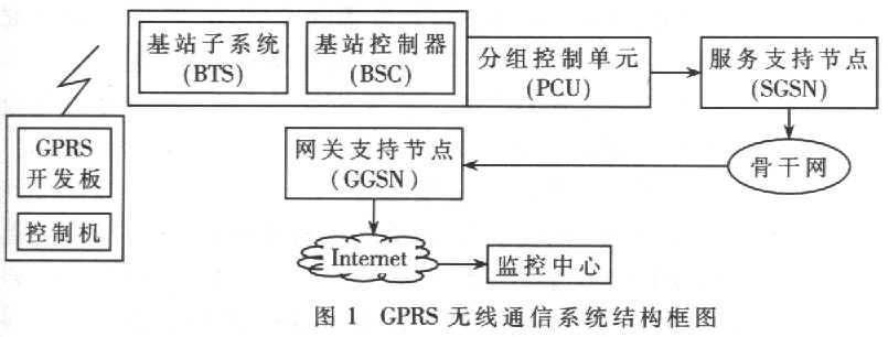
The mobile station connects to the reconstructed GSM base station (including BSC, BTS and PCU) through the GPRS module, and then connects to the GPRS service support node SGSN, communicates with the GPRS gateway support node GGSN through the SGSN, and the GGSN processes the packet data accordingly and sends to On the Internet, the communication between the mobile station and the monitoring center is realized.
The monitoring center is mainly composed of network servers and monitors. The data information of the mobile station is transmitted to the GPRS gateway through the GPRS network. The gateway sends these information to the network server of the monitoring center through the Internet through the IP protocol. The control information of the monitoring center is also delivered to the mobile station through this communication link: the TP packet with the mobile station address from the Internet is received by the GGSN, then forwarded to the SGSN, and then transmitted to the mobile station
2 Hardware Design of Image Transmission System The hardware part of the sending end of the system is mainly the MS part of the mobile station, including the mobile terminal (MT) and terminal equipment (TE). TE is the control machine, which is designed to use PC to implement communication control on MT. MT is mainly based on GPRS / GSM module, which needs to connect peripheral circuits to form a complete mobile terminal. The mobile terminal realizes various wireless communication functions by receiving AT commands sent by the controller
2.1 Functions and interfaces of GPRS wireless module
The GPRS module is the core of the entire mobile terminal, and the WISMO QUIK Q2406B module of WAVECOM is used. Q2406B is a GPRS10 level product, and the interface with external circuits is provided by a 60-pin universal connector. Q2406B belongs to the WISMO 2D series, which is fully compatible with WISMO 2C in terms of machine characteristics, mold reversal, software and hardware interfaces, including all the functions of the previous model modules. Because the optional TCP / IP protocol stack is embedded, Internet can be accessed directly through the AT command, eliminating the need for commonly used TCP / IP processing modules and the cumbersomeness of calling various API functions during programming. The functional interface description of the Q2406B module is shown in Figure 2.
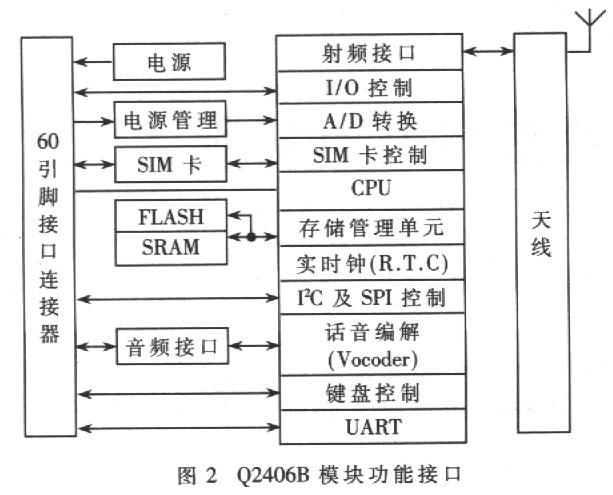
(1) Power interface: The power supply for the radio frequency part of the module is generally 3.6V, and the power supply for the baseband part should not be lower than 3.1V. A power supply that meets the ripple factor requirements can be used as input. Supply power to both parts at the same time.
(2) SIM card interface: provides compliance with GSMll. 12-standard 3VSIM card interface. If you want to connect a 5V SIM card (GSM 11.11 specification), you can connect an external 3 to 5V level converter (such as LTCl555).
(3) Voice input and output interfaces: including two microphone input and output interfaces.
(4) RF antenna circuit interface: There are direct and indirect antenna connection methods.
(5) I / O interface: including GPIO interface, uART interface, keyboard and SPI interface.
2.2 Realization of circuit function interface
The Q2406B module is connected to peripheral circuits. The hardware design block diagram of the mobile terminal is shown in Figure 3.
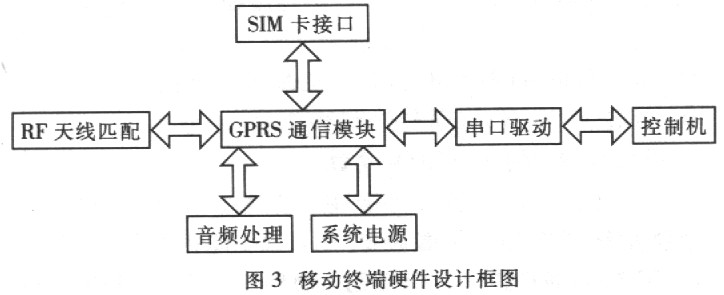
(1) Power supply: The external power supply should be stable. If it is less than 3.3V, the GPRS module cannot log on to the network; if it is greater than 4.5V, the module will be burned out.
(2) UART serial port: The mobile terminal communicates with the serial port of the controller through the UART, receiving AT commands and transmitting data. The Q2406B module is a TTL device. The serial port cannot be directly connected to the EIA-RS-232C connector of the PC. The MAX3237 is used to drive the serial port.
At least four signals are required for serial communication with 02406B: TXD, RXD, RTS and CTS. The latter two signals are used for hardware flow control to prevent data loss during transmission. See the communication software design section for details.
(3) SIM card interface: 3V SIM card detection signal output, but the Q2406B module provides the SIM card detection input pin SIMPRES, and the SIMPRES signal changes from low to high to indicate that the SIM card is inserted. To enable the module to detect the SIM card, the design is directly Connect the SIMPRES pin to high level.
(4) Audio processing: one of the two audio interfaces has its own offset, and one requires an external offset. The audio interface is internally connected to the op amp, and the differential mode is more conducive to preventing noise than the single-ended mode, so both channels are differentially connected, and the filter network composed of capacitors and inductors can be connected to the phone handle to make a call.
(5) The RF antenna matching uses an indirect connection method. Use a coaxial cable with an impedance of 50Ω to match the transmission impedance of the radio frequency part of the GPRS module. An antenna with an impedance of 50Ω is also connected to the other end of the cable, which greatly reduces the echo reflection and allows the device to move flexibly.
(6) The design also includes some auxiliary circuits: software download circuit, LED indicator circuit, switch and reset circuit, which can make the hardware platform work more efficiently and safely.
2.3 System Electromagnetic Compatibility Design Electromagnetic interference is a key consideration in wireless terminal design. The working frequency of the GPRS module is 900/1 800MHz, and the peak value of the transmission power reaches 2W. Improper handling will cause interference to the peripheral circuits. Overcome all kinds of interference. Ensuring stable work is the primary consideration of layout. The design takes measures from the following aspects:
(1) Try to use SMD packaged devices, avoid DIP type devices, reduce the current emission (induction) loop area, and save the board area.
(2) A four-layer PCB board is used to ensure the integrity of the signal and power supply, avoid loss during transmission, and minimize power supply and ground bounce noise. Good grounding can also play a better role in electrostatic protection and heat dissipation, the design uses the same ground wire for all signals (analog / digital, radio frequency).
(3) Focus on key signal wiring. In order to protect sensitive parts such as SIM card and serial port output from radio frequency and peak pulse interference, high-speed anti-static tubes ESDA6V1L and DAI6V1L are used for protection; audio signal lines are isolated and shielded with ground wires to reduce external interference.
(4) Reasonably arrange the position of the device, reduce the length of the trace, and the length of the SIM card interface line should be less than lOom.
(5) Add decoupling capacitors next to the power supply line to ensure stable power supply.
2.4 System thermal protection design
The working temperature of 02406B is 20 ~ 55 ° C, and the RF transmission power is relatively large. The heat dissipation design should be carried out to prevent the heat generated by long-term work from burning the module.
(1) Solder the ground pins on the isolation cover of the Q2406B module to both sides of the PCB at the same time to accelerate the heat dissipation of the module.
(2) Choose an antenna that matches the radio frequency of the GPRS module to reduce the heat generated by the antenna's echo reflection.
(3) The component layout should also pay attention to heat dissipation: the high-power GPRS module is placed sideways to facilitate heat dissipation; the transmitter antenna accessories do not put components, especially capacitors, to avoid premature aging of the electrolyte by heating.
3 Software design of image transmission system
3.1 Design purpose Software design purpose: by sending AT commands to the GPRS module to control the communication process of the mobile terminal, so that the mobile station can access the Internet through the gateway and routing provided by GPRS, and complete the Internet with TCP / IP network protocol The task of monitoring center to transmit image data.
Based on the above requirements, communication software, namely GPRS client software and server-side software, is designed.
3. 2 GPRS wireless module communication instructions
The software part of the WISMO 2D module provides an external AT command set to control the operation of the system. By receiving the AT command from the UART, it interprets and executes the corresponding operation to realize the corresponding function of the wireless modem.
Because the program written is too long, only the main AT commands used for TCP transmission are listed:
AT + CGREG = 1; // Set GPRS registration status
AT + CGATT = l; // GPRS network attachment
AT # APNSERV = "CMNET"; // Set GPRS access point
AT # APNUN = "" "; // The identity verification user name is set to blank
AT # APNPW = "" "; // The authentication password is set to blank
AT # ConnecTIonStart; // Connect to the CPRS network to log in to the Internet, and successfully return the dynamically assigned IP address
AT # TCPSERV = “202.112.135.203â€: // Set the server IP address, that is, the IP address of the monitoring center
AT # TCPPORT = “6000â€: // Set Socket port for communication between server and client:
AT # otcp; // Open TCP connection with remote server
After the TCP connection is successful, the GPRS module enters the data transmission state. At this time, the image data can be sent to the GPRS module through the serial port, and the module can be sent to the monitoring center through the Socket. The monitoring center can also send response data to the module. After the data is transmitted, the controller sends a termination character to the GPRS module
3.3 GPRS client software The client software running on the control machine has the following functions:
(1) Serial communication, including AT command communication and data file communication.
(2) Display the transmission process timing, used to test the transmission rate of the system.
(3) Terminate the GPRS module TCP protocol stack communication. When the system transmission error occurs, the protocol stack is suspended.
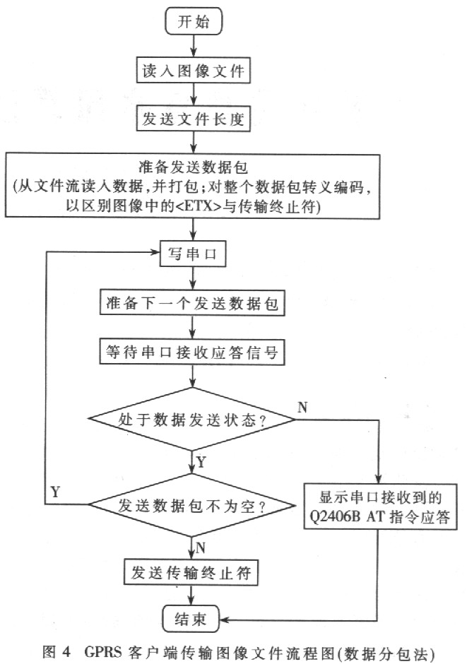
Q2406B has a limited buffer area for the embedded TCP protocol stack. If the serial port write rate is much higher than the GPRS transmission rate, the protocol stack will lose data. To ensure the reliability of data transmission, flow control must be performed. Two flow control methods are used in the design: data packetization method and hardware handshake method.
The flow chart of image file transmission by GPRS client using data subcontracting method is shown in Figure 4. In this method, the image file is first divided into several small data packets, which are written into the serial port one by one and sent by the GPRS module. After receiving a data packet, the server of the monitoring center returns a response frame, and the GPRS module sends the next data packet. If the response frame has not been returned within the timeout, the last data packet is resent. This method sacrifices a certain amount of time, but it well guarantees the reliability of image transmission
The hardware handshake method uses the hardware handshake signal in the 9-wire serial port: RTS / CTS for flow control. When the system is working. The control machine uses RTS to start the data flow of the GPRS module, and the GPRS module uses CTS to start and pause the data flow from the control machine. When the amount of data in the cache area reaches a high level, the module sets the CTS line to a low level. After the control program detects that CTS is low, it stops sending data until the amount of data in the protocol stack cache area is lower than the low position and sets CTS high Level.
This method can also ensure that the written data is not lost, and the time taken to transfer the image file is lower than the previous method. However, it cannot be used for the simplified three-wire serial protocol, nor can it detect packet loss during GPRS data transmission as in the previous method, and ensure the reliability of the transmission process by retransmission.
3.4 GPRS server software
GPRS image transmission system adopts the method that multiple mobile terminals are connected to the monitoring center server. The server adopts the host mode on the ordinary Internet. As a TCP server, it has a static public IP and opens a listening port, which can be accessed from the outside. It runs a TCP port listening program, receives TCP packets from the mobile station, and sends The mobile station sends response data. The process of receiving image files on the GPRS server using the data subcontracting method is shown in Figure 5. The server-side software has the following functions: (1) monitor TCP port; (2) receive data packets, send and receive response frames; (3) display received data and size, save image files.

The sender of this system has designed two flow control methods, one is implemented on hardware and the other is implemented on software. The former has a faster transmission speed when the network conditions are stable. The latter can effectively ensure the stability and reliability of the entire GPRS transmission process, and can be directly used for the simplified three-wire serial port protocol. When the embedded microprocessor is used in the control machine, it can be easily connected to the serial port of the microprocessor without serial port conversion chip.
Using the ordinary GPRS service provided by China Mobile for testing, the transmission rate of this system can reach 10kbps. There is no loss of data in a large number of tests, and the entire system works stably and reliably. At the same time, it is also capable of transmitting any form of file data, which is used in systems that need to transmit data remotely.
984 controllers are available in four generic hardware classes: Large, rugged, high-performance chassis mount controllers Rugged, midrange-performance slot mount controllers, which reside in a primary housing beside 800 Series I/O Modules Host-based controllers built on various industry-standard computer cards designed to reside in and execute control logic from a host computer Low-cost, easy-to-install compact controllers, for applications with less demanding environmental and performance requirements The family approach to 984 controller design allows you to make choices based on controller capacity (the number of discrete and analog/register points available for application programming, the number of I/O drops it supports), throughput (the rate at which it solves logic and updates I/O modules), and environmental hardness (the design standards its hardware implementation must meet).
A major advantage of the family approach to 984 controller design is product compatibility. Regardless of its computational capacity, performance characteristics, or hardware implementation, each 984 controller is architecturally consistent with other 984s. The 984 instruction set (the functional capabilities of the controller, part of the system firmware stored in executive PROM) comprises logic functions common to other 984s. This means that user logic created on a midrange or high-performance unit such as a 984-685 or a 984B can be relocated to a smaller controller such as a 984-145 (assuming sufficient memory in the smaller machine) and that logic created on a smaller controller is upwardly compatible to a larger unit. As your application requirements increase, it is relatively easy to upgrade your controller hardware without having to rewrite control logic. Also, training costs and learning curves can be reduced, since users familiar with one 984 model automatically have a strong understanding of others.
Modicon PC0984 Programmable Controller
Modicon PC 0984 Programmable Controller,Communication Processor,Processor Module,CPU Module
Xiamen The Anaswers Trade Co,.LTD , https://www.answersplc.com