With the increasing complexity of SoCs and SIPs in high-volume consumer industries, the contradiction between the two basic requirements of low cost and high device life cycle is more prominent. Consumers demand improved performance on the same or lower cost basis, while often making new improvements. Therefore, components must be thoroughly tested at low cost and extremely fast.
This article refers to the address: http://
While greatly reducing the ATE architecture throughput overhead, it can provide more parallel processing capabilities in the test, which may properly solve the additional time problem caused by testing increasingly complex devices. In order to solve the emerging analog core problem in leading-edge consumer devices, in addition to the above two measures, the resolution and accuracy of the ATE hardware must be guaranteed.
Audio DAC and ADC
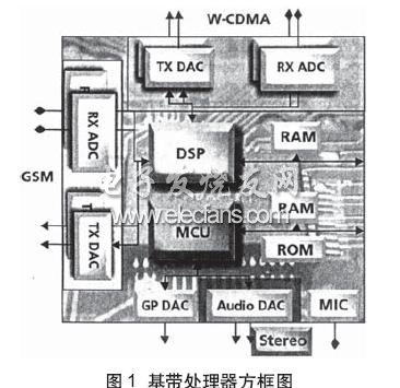
The highly integrated SoC device, shown in Figure 1 of the wireless handset baseband processor, has multiple functional blocks with different performances that are subject to the dual pressures of specification and test time.
The simple 10-bit effective resolution and 4KHz bandwidth meet the audio quality requirements of early wireless handsets. The latest trends show that the device can support the more stringent CD-quality audio performance, stereo and surround sound effects. The market claims to have 24-bit audio resolution, the actual effective performance is generally 16 to 17 bits, equivalent to 98dB to 104dB dynamic range, bandwidth is 20KHz.
When consumer uses discrete CD-quality DACs and ADCs, ATE-related test costs can be met due to the initiative to increase device price. When the CD quality core is integrated in the SoC, the additional function increases the test time and the negative impact on the test cost (COT), and the increase in the price of the device cannot compensate for the increase in the cost of the ATE test.
Audio core test time derivation example
Dynamic testing of mixed signals is essential to prevent leakage of the spectrum in the spectrum generated during the analysis. Therefore, the following relationships must be met:
M/N=Ft/Fs
Where M is the number of capture cycles; N is the number of sample points; Ft is the test signal frequency; Fs is the sampling frequency.
For low-fidelity audio devices, such as ADC input microphones or DAC output headphones, the 8KHz sampling frequency is equivalent to 4KHz bandwidth. If the test signal frequency is 1.03125KHz, 66 cycles can be captured relative to the 8KHz sampling frequency and 512 point acquisition. The sampling time is equal to the number of sampling points divided by the sampling frequency, which is 64ms. Audio testing requires more than 10 tests, including multiple gain states; idle channel noise (ICN), crosstalk (XTALK), and intermodulation distortion (IMD), so that even for simple cores, the total test time is also It takes 650ms.
The test overhead is also very impressive by transferring 20 bits of sampled data from the analog or digital capture memory of the ATE to the workstation. In order to determine the amount of data transfer for analysis, 20 bits are multiplied by the number of sample points N and multiplied by the number of test quantities of the test core. In this example, 20 bits × 512 points × 10 measurements, totaling 102,400 bits. Assuming a bandwidth of 1 MB between the analog module and the workstation, the test DAC core has a transfer time of approximately 100 ms. The digital capture memory transfer overhead is also 100ms at the same bandwidth. Therefore, for voice quality DAC and ADC testing, the 200ms transmission overhead increases the total test time to 1500ms (650ms + 650ms + 200ms).
Parallel test overhead for ATE architecture
To further illustrate this issue, consider the impact of surround sound audio processors on test time. AC3 digital audio provides 6 analog outputs: front L/R; surround L/R; center speaker and ultra low single speaker. From a simulation perspective, these devices require a combination of high dynamic range and parallel testing.
The CD quality dynamic range and bandwidth require a higher sampling rate. Using the above formula and replacing it with Fs = 4.8 KHz, the sampling time is 10.7 ms. Taking into account hardware settings, test stability and other overhead, the test time takes 15ms. Taking into account the number of measurements more than 10 times, the total test time rises to 150ms. This will require 900ms for a serial test implementation for 6 channels per location.
4 test point implementations can take advantage of the parallel testing of multiple waveform digitizers. However, data transfer is still serial in multiple test point tests, and the transfer overhead is cumulative. Therefore, even with 4 waveform digitizers, the 4 test point test implementation requires 900ms + 4 x 600ms = 3300ms.
Multi-standard wireless baseband processor
Wireless devices have multiple standards set up in the same phone. To support these standards, the chipset often has redundant baseband analog converters and RF transceivers. As in the audio surround sound processor, many analog cores in the wireless baseband processor have a huge impact on test time. The main challenge in testing these devices is how to set up enough parallel tests in the simulation test hardware to get the efficiency of multiple test points.
The baseband processor block consists of a quadrature (I/O) transmit (TX) DAC and receive (RX) ADC pair. In the 2G to 2.75 GGSM/GPRS/EDGE technology, the carrier channel spacing is limited to 200 KHz, resulting in a low frequency zero IF. W-CDMA uses a 5MHz channel, and the corresponding bandwidth is wider.
The RX and TX paths typically require full dynamic testing, including signal-to-distortion (SND), CIN, and XTALK. I/Q also requires gain matching and phase matching tests for the DAC and ADC. The specifications are specified in 0.1 dB and 3 degree precision, respectively. The requirement for channel isolation during transmission results in additional out-of-band (00B) attenuation testing of the DAC. The adjacent channel power ratio (ACPR) can confirm the degree of channel isolation. For W-CDMA DACs, the tested OOB frequency is as high as 10 MHz.
High definition video encoder
Current SoC devices support multiple video input standards. Traditional NTSC or PAL devices are equipped with Super Video CS-VIDEO and composite analog outputs. Support for HDTV requires three additional outputs to provide a signal that is compliant with YPrPbHDTV (EIA-770.1-3). It is necessary to use 6 video DACs for all the above outputs: 2 for S-Video, 1 for composite output, and 3 for RGB.
Although the highest required interface speed for digital video standards is 74MHz, the analog bandwidth required to test DAC performance is approximately 8MHz with a resolution of 10 to 12 bits. Typical test items for a single video DAC include integral nonlinearity (INL), differential nonlinearity (DNL), and SND measurements. The graphics quality of the HDTV system is determined by the relative accuracy of the DAC output, and additional tests must be performed on the output gain and phase matching. The total test time for a built-in digital video device is directly related to the number of parallel digitizers available for testing. The number of video DACs to be tested is usually more than six. Due to the lack of tester resources, it is essential to establish a serialized test solution. Parallel test scheme
Although reducing the total COT is affected by multiple variables, implementing multi-point testing and parallel testing to improve throughput is undoubtedly the primary method. The latest generation ATE system uses a multi-port architecture that supports a group of tester resource structures that match the functionality of the device under test.
The two main functions to achieve the above objectives are the per-port timing generator and the per-port sequencer, the former matching the frequency of the test core; the latter operating in different test modes and automatically executing sequence instructions. Each pin multi-port scheme goes one step further than the above scheme, subdividing the granularity of the digital and analog resources of the ATE system into each pin. Examples of necessary resource structures for testing typical SoCs include: DSPs used as communication processors, memory, and ADCs and DACs that interface with analog IF or RF front ends. In this case, the digital pins are configured in scan mode to test the DSP core (see Figure 2).
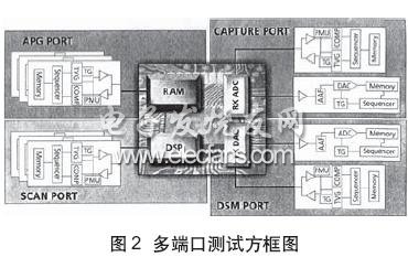
The ADC block requires an arbitrary waveform generator (Arb) and a digital channel in capture mode to acquire and analyze the output of the ADC. The DAC requires a port of multiple digital channels to be tested with a digital source memory (DSM) or waveform memory segment and a waveform digitizer. Each port can automatically operate at different test frequencies and execute different sequence instructions.
Since the test system is segmented on a per-pin basis, by copying the image of the test vector and the sequence of pins used at each test point, the application automatically manages the control of most of the multiple test points.
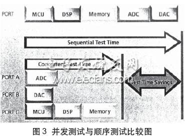
Concurrency testing is an extension of multiport testing that allows these cores to be tested in parallel. Of course, each core in the device should be independently accessible and controllable by the ATE system and can operate independently. Modifying the pure sequence stream for each device core serial test to a sequence stream for parallel testing of multiple device cores can greatly reduce test execution time (Figure 3).
In large-scale devices (such as wireless baseband SoC processors), there are countless analog cores, and testing these cores in parallel requires a large amount of analog resources. If you press 4 test points, full parallel, concurrent test calculations, you need to provide 28 digitizers, which is still difficult to achieve in current ATE systems.
A new module architecture
Testing a variety of analog cores used in current consumer devices requires a highly parallel, low-overhead solution. If several module functions are combined in each module, the space occupied by each analog module can be reduced accordingly, so that more space is reserved for the necessary digital modules. A module with 8 independent Arb or digitizer units has the advantage of flexible configuration: either as a digitizer unit or as a combination of digital and Arb units.
The COT that reduces consumer device testing not only addresses the parallel testing scheme of the ATE test system, but also reduces the ATE overhead caused by parallel testing. Multi-core core is the main feature of current SoC consumer devices. The above two factors should also be considered in the architectural improvement of ATE hardware, in order to get the best test solution.
Function: The Led Head Lamp has 1-5 modes;
Feature: The LED Head Lamp usually high power and super bright;
Trait: The products are waterproof, shockproof and tactical;
Method of application: Simple on/off push button operation, or motion sensor;
Range of application: The LED Head Lamp for emergency events, camping, outdoor activities;
Adervantages: Our products are saled with factory price, and the quality can guarantee, lastly we provide warranty for 1 year.
LED Head Lamp
Led Head Lamp,Headlamp Torch,Led Headlamp,Led Head Torch
Ningbo Henglang Import & Export Co.,Ltd , https://www.odistarflashlight.com