Image compression coding and decoding principle
This article refers to the address: http://
This section introduces the basic principles of image compression coding, the basic structure of image data compression and decompression circuits. They are the basics of looking at the circuit diagram of a DVD player.
First, the basic way of image compression
The amount of data in an image is extremely large and must be greatly compressed in order to be stored on a 12 cm diameter disc. In practical technology, the total amount of image data can be compressed by the following means.
1, using brightness (Y), chromaticity (C) sampling method
The practical color television technology does not transmit and process three primary colors of red, blue and green, but transmits and processes the luminance signal Y and the chrominance signal C. This processing method is advantageous for achieving compatibility between color television and black and white television, and also for limiting the bandwidth of the color television signal. In the digital image processing technique, a method of transmitting and processing the luminance signal Y and the chrominance signal C is still employed. Since the human eye is sensitive to luminance information and is not sensitive to color information, the Y signal is transmitted with higher definition and the C signal is transmitted with lower resolution. The actual practice is as follows: each luminance Y pixel is transmitted; and the chrominance C is decomposed into U, V two color difference signals (or written as Cb, Cr, BY, RY), respectively, for transmission; Pose-by-point sampling is performed, while chrominance C is sampled less. That is, corresponding to the four luma sampling points, only one point is sampled for the chroma signal, that is, the U and V pixels are sampled lower, and each sampling point is taken. This sampling format is called YUV411 format.
With the YUV411 sampling format, its total data will be reduced by half compared to the three primary color sample format. If three primary color sampling methods are used, each primary color should be sampled in the same manner as the luminance signal, that is, a method of sampling point by point for each red, green, and blue. When the Y and C transmission modes are used, the number of sampling times is reduced by half, and the transmission number is also reduced by half. The human eye is less sensitive to chromaticity. Using the physiological visual characteristics of the human eye, people do not feel the sharpness of the image in subjective perception. Obviously, this is a powerful measure to compress the image data rate.
2. Divide the entire image into small areas for segmentation processing. <br> When data is processed for an image, each frame of image is segmented. First, the image is cut into several strips horizontally, each strip is called a slice, and each slice is longitudinally cut into several blocks, which are called macroblocks, which are the basic units of image compression. The color image of each macroblock can be represented by one luminance signal Y and two color difference signals Cb, Cr (ie, U, V), or each macroblock is divided into three layers, one layer of luminance Y, two layers of colors. Degrees (each Cb, Cr) are collectively referred to as a macroblock.
Since the subjective sensitivity of the human eye to brightness and chromaticity is different, the luminance macroblock is usually equally divided into four blocks, each of which is called a block or a block. See Figure 2.2.1 for details. Each block can be further divided, called a pixel or pixel, and the pixel is the smallest unit that makes up the image. For digital images, each pixel has a corresponding sample value as a sample point. It can be seen that the finer the image segmentation, the more the number of pixels, the more the sampling points, the higher the image sharpness; conversely, the fewer the number of pixels, the lower the image sharpness. In fact, for image compression processing, data of an image block and data of a pixel are compressed. 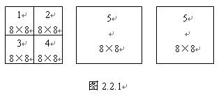
The color data system is different, and the specific data of the segmented image will change. For example, PAL system, most of which is 625 lines of scanning standard, then each frame of image is cut into 18 pieces, each piece is then cut into 22 macroblocks, that is, each frame of image is divided into 396 macroblocks; and 525 lines of NTSC system, each The frame image is cut into 15 slices, and each slice is further divided into 22 macroblocks, that is, each frame of the image is divided into 330 macroblocks. For the luminance signal, each macroblock is further divided into 4 blocks, each block containing 8 × 8 = 64 pixels, and each macro block contains 256 pixels. However, for two color difference signals, the number of macroblock pixels is equal to the number of block pixels, that is, the number of pixels is 8×8=64, which is 1/4 of the luminance pixel. Although the two color difference signals have fewer pixels and low definition, they do not affect the subjective feeling of the human eye. When digital image processing is performed, the 8×8 blocks (64 blocks in total) are arranged in order, and then processed in order of number. That is to say, a block of 8 × 8 pixels is used as a basic operation unit, and sample values ​​of each pixel (i.e., sampling point) are sequentially processed.
3. Adopt inter-frame and intra-frame data compression techniques.
The utility TV transmits 25-30 frames per second to make the picture change continuous, and the TV moving picture is composed of a series of pictures with little difference between frames. The small changes in the frame picture are mainly reflected in the main part of the picture, and the background difference of the picture is small. The image is described by luminance and chrominance information. In each adjacent frame image, if the luminance and chrominance signals of the same relative position are respectively compared, the difference is usually small. According to a large number of statistics, the luminance difference of only 10% or less of the pixels is changed by more than 2%, and the chromaticity difference is less than 0.1%. There is a large amount of duplicate content in each frame image, and the data of these duplicate contents belongs to redundant (redundant) information, so that the digital transmission of images can be reduced by reducing the time domain redundant information, that is, operating interframe data compression technology. rate.
It is found through analysis that there is also a considerable amount of redundant information in the same frame. The part that is most sensitive to the main part of the image and the eye should be processed accurately and in detail, and each pixel should be finely transmitted. However, for parts that are not sensitive to the part of the image and the eyes, rough processing can be performed, that is, Compression processing of information data. Therefore, according to the specific distribution of the image content of one frame, different data quantities can be transmitted for different positions, the data amount of the transmitted image is reduced, and the image data is compressed. This method of compressing data is to perform data compression in different spatial parts of the same frame image, which is called spatial domain redundancy compression. For example, there is a portrait picture, the line definition of the face and head can be different, especially the eyes and lips are rich in expression, the lines are more complicated, and it is the most noticeable part of the audience, which should be transmitted in high definition; The side and cheek side have less contour changes, and the gray level changes little, and the viewer does not pay much attention to these parts. Obviously, the main part of the image, the part where the gray level changes greatly, the part sensitive to the human eye should be finely transmitted with a large amount of data; and the minor part of those images, the part with small change of the gray level, person Where the eyes are not paying attention, coarse transmission can be performed with a small amount of data, and even only their average luminance information is transmitted.
The principle of data compression for digital images is discussed in detail below. Firstly, the data compression technology of still image is discussed, that is, the intraframe data compression technology; then the data compression technology of the moving image, that is, the interframe data compression technology is discussed.
Second, the intra-frame data compression technique first performs segmentation processing on the entire image, and obtains a minimum operation unit by segmentation. The following is a block of 8 × 8 = 64 pixels. Each pixel value can be sampled according to a certain rule. For example, the luminance value of each pixel of the luminance can be sampled. If each pixel is quantized by 8 bits, the total data amount of each block is 8 bit × 64 (pixel point), that is, 512 bit. . It can be seen that the amount of data after the quantization processing of each pixel of the full picture is very large, and data compression is required. Usually, after discrete cosine transform, zigzag scan, variable length coding and other processes, the total amount of data can be compressed a lot.
1. Discrete Cosine Transform (DCT) coding
(1) Function Description Discrete cosine transform is abbreviated as DCT (an abbreviation of Discrete Cosine Transform), which is a digital processing method and is often used for data processing. DCT is a kind of digital conversion method, which is a method of transforming a spatial domain image into a frequency domain for analysis. Since the base vector formed by the transform kernel of the DCT is independent of the image content, and the transform kernel can be separated, the two-dimensional DCT can be completed by two-dimensional DCT, which greatly simplifies the mathematical operation and is matched with other found ones. Fast algorithms make DCT coding widely used. Applying DCT to image data compression can reduce the hierarchical digital information representing image brightness (or chrominance) and achieve data compression. With DCT, not only can the image be encoded, but also the position of the image detail can be found in the process of coding transformation, in order to delete or omit the part that is not sensitive to the vision, and highlight the sensitive part of the vision, and transmit and value the image by selecting the main data. .
The use of DCT to compress image data is mainly based on the statistical properties of the image signal in the frequency domain. In the spatial domain, the image content varies widely; but in the frequency domain, after statistical analysis of a large number of images, it is found that after DCT transform, the main components of the frequency coefficient are concentrated in a relatively small range, and mainly located in the low frequency part. After revealing this rule by DCT transform, some measures can be taken to discard the less energy part of the spectrum, and the main frequency components in the transmission spectrum are retained as much as possible, so that the image data compression can be achieved.
(2) Laws and characteristics 1 The spectrum of the time domain signal is a periodic signal that changes with time for a waveform that changes with time. It is a DC average value of a waveform with a certain amplitude value, and its waveform can be regarded as The fundamental wave is superimposed with numerous harmonics. The amplitude of the fundamental wave is the largest, and then the amplitude of each harmonic gradually decreases. The higher the number of harmonic superpositions, the closer the synthesized waveform is to the ideal rectangular wave. This analytical method is the application of an increasingly broad spectrum analysis method. The amplitude values ​​of the sinusoidal harmonics are often referred to as spectral coefficients, and the spectral coefficients are arranged to form a coefficient column. The above facts show that the periodic rectangular wave can be described by the time domain (reflecting the amplitude-time relationship) or by the frequency domain (amplitude-frequency relationship). The two have a corresponding relationship. In fact, various time domain signals can be described by the laws of the frequency domain. The two description methods are intrinsically linked and can be converted to each other.
2 Spectral coefficients of spatial domain signals For signals distributed in various spatial domains, similar frequency transforms can be performed, that is, the spatial domain signals are converted into frequency domain signals. DCT is one of the methods of frequency analysis. The DCT transform process can be illustrated by referring to Figure 2.2.2.
A block is taken from the image and divided into 64 arrays of 8 × 8 pixels, that is, from (a) to (b). The values ​​of the pixel-by-pixel luminance (or discussion chrominance) are sampled, and the luminance values ​​of the pixels are listed in a matrix form, as shown in Figure (C). Then use discrete cosine transform (DCT) to transform each spatial sample value 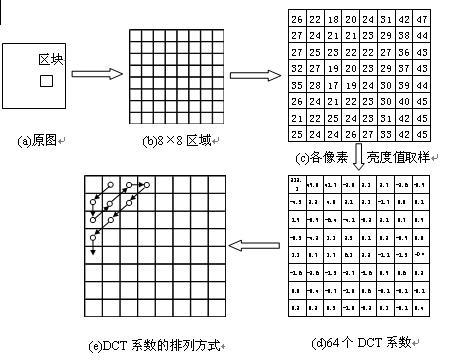
The value of the frequency domain is referred to herein as the DCT coefficient.
For the 64-point array described above, 64 DCT coefficients can be obtained and converted into a rectangular array table of (d). It has converted an array of 64 points of image sample values ​​into a 64-point array consisting of a DC average and 63 different frequency cosine wave amplitudes, and is called a DCT coefficient array. After the above transformation, the data of the spatial coordinates has been converted into the data of the frequency coordinates, that is, the DCT frequency coefficient. After the numerical samples of the original 8×8 blocks are sampled and quantized, they are converted into the spectral coefficients of the frequency domain image signals, which can be expressed by 64 frequency coefficients, which are called 64 “orthogonal base signalsâ€, each base The signal corresponds to one of 64 independent two-dimensional spatial frequencies. These spatial frequencies are composed of the "spectrum" of the input signal. Among the 64 transform coefficients obtained, the first term represents the DC component, that is, the average of the 64 spatial image sample values, and the remaining 63 coefficients represent the amplitude of each base signal.
Observe the data in Figure 2.3.2(d). The value in the upper left corner of the matrix is ​​larger, while the value in the lower right corner is smaller and close to zero. Thus, the DCT coefficients of the respective base signals can be arranged into a table in the zigzag scanning order. The specific trajectory of the zigzag scan is shown in Figure 2.3.2(e). According to this rule, the DCT coefficients are arranged into a data series to become a DCT coefficient coding sequence. After the above processing, the two-dimensional data amount has been converted into a one-dimensional data amount, and the first item of the series is the average brightness value of the block, and the distribution and size of the subsequent coefficients can reflect the severity of the brightness fluctuation. If the coefficient is large, the brightness fluctuation is large, and the image contour of the area is fine; if the value is small, the brightness change in the area is relatively gentle; if the value is zero, the high frequency component value in the series is zero, the brightness level No change. In the actual data processing process, the coefficient values ​​that are listed later basically have a value of zero or tend to zero. From 63 sets of coefficients and changes, it can reflect the details of the image in the block, that is, the image clarity.
Figure (d) matrix values ​​are very practical. The upper left corner has a large value, which represents the DC component and the low frequency component of the image information. It is the main part of the image information and the main part of the information in the block; while the lower right corner value is small, they represent the high frequency of the image information. The component, its amplitude is originally small, it mainly reflects the details of the image. The human eye has a relatively high sensitivity to the brightness information of the image and is not sensitive to the color information of the image; and the human eye has a high visual sensitivity to the low frequency component of the image information. The data series formed by scanning the zigzag characters form a good correspondence with the sensitivity of the human eye to the image information. The image data can be compressed according to the above laws of visual physiology.
2. Requantization processing of DCT coefficients The frequency data processed by the above DCT can be reprocessed to further compress the amount of data. The human eye is sensitive to various frequencies and can obtain statistical sensitivity values. Therefore, different conversion values ​​can be set for each frequency component, and the converted DCT coefficients can be converted again to further highlight the components whose visual effects are large, and weaken or ignore the components with small visual effects. This processing method is called quantization processing, referred to as Q processing. For the 64 coefficients of the 64-point array, corresponding to 64 different frequencies, 64 different conversion values ​​can be used. These 64 conversion values ​​are usually called quantization tables, and each conversion value is called a quantization step size, or a quantization value. In the 64-point array, the data quantization value in the upper left corner is smaller, and the data quantization value in the lower right corner is larger. The requantization processing of the DCT coefficients can be implemented using a quantizer circuit. The circuit can divide the 64 coefficients of the block by the corresponding position quantization step size in the quantization table, and then perform rounding and rounding to obtain 64 data values ​​after re-quantization processing.
After the quantization process, the quotient value of the coefficient value with large quantization value is small, that is, the data compression is relatively large, and the corresponding content of the original image is more neglected; the coefficient with smaller quantization value has larger quotient value, that is, data compression comparison Small, the corresponding part of the original image is not ignored or minimally ignored. Thus, after the quantized DCT coefficient matrix, many zero values ​​can occur. Generally, the quotient of the data in the upper left corner position is non-zero, and the quotient of the data in the lower right corner position is small, and can be abbreviated as 0 after rounding off the integer value. A large number of zero values ​​appear on the coefficient matrix, which greatly reduces the amount of data. On the one hand, the main part of the image information is retained, and on the other hand, the image data is greatly compressed.
3. Variable length coding (VLC)
The quantized coefficient matrix shows a lot of zero values. If a zigzag scan is performed, the subsequent coefficients will also appear as consecutive zeros. At this point, the total amount of data transmission has been significantly reduced, but the code point has not decreased, still 64 coefficient bits. In order to further compress the total amount of data, variable length coding may be employed, and VLC (Variable Length Coding) is abbreviated.
Generally, two methods are used for variable length coding. The first type is to replace the code words with different lengths according to the frequency of occurrence of the data. For frequently appearing data, short code words are allocated, and those that do not often appear are given longer code words. This process reduces the total code rate of the transmission. In the second method, although the zigzag scan causes a plurality of zero values ​​to appear at the tail of the coefficient column, it is not necessary to transmit the value of 0 bit by bit, and only the "number" code of the table 0 needs to be transmitted, and then resumes as required when replaying. It is 0 bits to fill the 64 bits of the matrix. For example, 00000 can be expressed as 50, and restored to 00000 at the time of decoding.
In short, for still pictures, discrete cosine transform, zigzag scanning, quantization processing, and variable length coding can be used to greatly compress the amount of image data. In the data decoding, the variable length decoding is firstly restored to the fixed length of the data; then the coefficients are inverse quantized and restored to the original DCT frequency coefficients; and then inverse discrete cosine transform is performed to restore the spatial coordinate values ​​of the image. That is, the data of the original image.
Third, the inter-frame data compression technology For moving images, the images of adjacent frames have a strong correlation. When saving and recording a moving image, it is not necessary to record and save all the information of each frame of image. All the data of the first frame of the previous frame can be recorded, and it can be regarded as a static image, which can be compressed by static image data. Method to handle. With the subsequent frame images, only information different from the previous frame image can be recorded. Thus, at the time of playback, the image of the subsequent frame can be recovered by using the data of the previous frame image and the difference data of the subsequent frame. This processing method saves a lot of data.
1. Three kinds of pictures According to the MPEG-1 standard, the moving pictures transmitted can be divided into three types. The first type is the first frame after the scene change. It is an independent picture. This picture is transmitted by the higher-resolution point-by-point sampling method. This picture is called I picture (internal frame, or Called intraframe encoded frame). The picture information is determined by its own picture, and it is not necessary to refer to other pictures. The data of this picture represents the main content and background content of the moving image, which is the basis of the TV picture. The second type is a picture in which the moving picture main body position has changed significantly on the same background from the I picture for a certain period of time. This picture is called a P picture (predicted frame, or forward predictive coded frame). This picture uses the previous I picture as the reference picture, which does not transmit repetitive information such as background, only transmits the difference of the subject change, which omits part of the detail information, and relies on the frame memory to reproduce the main picture of the I picture during playback. The difference between the partial and P pictures is calculated, and the complete content of the new picture can be obtained. It is the actual picture with both the background and the current moving subject state. The third type, which is similar to the P picture, is used to transmit pictures between I and P pictures, called B pictures (bidirectional prediction frames, or bidirectionally predicted interpolated coded frames). This screen reflects only the change in the motion subject between the I and P screens, and uses the displacement vector (or motion vector, etc.) to indicate the movement of the screen subject. The amount of information is smaller. Since it can refer to both the I picture content and the P picture content when playing back it, it is called a bidirectional prediction frame.
After dividing a series of consecutive related pictures into I, P, and B types, the amount of transmitted information is significantly reduced. In the P and B pictures, almost no pixels reflecting the real object are transmitted, and only the difference of the movement of the main body is transmitted. The specific processing method is to use the method of block comparison, and among the two changed pictures, the block is used. Or the macroblock as a processing unit, compares the macros and blocks of a picture with the macros and blocks in the adjacent range of the participating pictures, and searches for the block closest to the block with the smallest error, and finds the approximate area. After the block, the displacement values ​​of the block in the two pictures are recorded, that is, the displacement vector and the difference amount reflecting the two pictures. If the displacement vector coordinate changes to 0, it means that the block has no movement, such as the same background scene; if the displacement vector value changes, and the block difference is 0, it means that the scene has movement, and the shape has no change, such as in flight. Balls and Mercedes-Benz vehicles, etc. It can be seen that the displacement vector and the block difference can rely on the reference picture to obtain a complete scene of the new picture during playback, while the background and the body content are omitted when transmitting, and only a small amount of data representing the displacement vector and the difference is transmitted, so that the image is made. Get a lot of compression.
2. Connection of three kinds of pictures Generally, the first frame after replacing the scene is an I frame, and the I frame should be transmitted in full frame. From the perspective of compression, the I picture has the least amount of compression; the P picture is second, it is based on the I picture; B picture compression is the most. In order to increase the compression ratio, usually one frame is separated by 2 frames (up to 3 frames) behind the I frame, and B frames are used between I and P frames, and 2 to 3 frames are also set between the two P frames. B frame. The B frame transmits the difference information between it and the I frame or the P frame, or the difference information between the P frame and the following P frame or I frame, or it is equal to the average of the I and P frames or the P and P frames. Difference information between. When the content of the main body changes more, the frame value between the two I pictures is smaller; when the content of the main body changes, the interval of the I picture can be appropriately larger. In other words, the larger the proportion of B frames and P frames, the higher the image compression ratio. Generally, two I pictures are separated by 13 to 15 frames, and the number of separated frames should not be more.
The following takes 15 frames as an example to illustrate the order in which VCD image frames are arranged. The typical setting of the three screens of I, P, and B takes about half a second for the NTSC system. The order of program input is arranged in the order of actual appearance, namely I, B, B, P, B, B, P, B, B...I, B, B, P...; but for the convenience of decoding from I, P The picture is interpolated to obtain the B picture. When encoding the recorded program, the order is changed, that is, in the order of I, P, B, B, etc., that is, the original 0, 3, 1, 2, 6, 4, 5, The order of the pictures of 9, 7, 8... When decoding, 0 frames and 3 frames are first solved, and then 1 frame, 2 frames, and the like are calculated by interpolation prediction. To this end, dynamic memory must be set in the decoder, the I and P frames are decoded and stored first, and then each B frame is calculated. However, in the final output, it should be reorganized in the actual playback order and output in the correct order.
The interframe compression technology standard adopted by VCD has specific specifications for image coding order and frame interval. After the frame compression technology is adopted, the information redundancy between frames is greatly reduced, the image bit rate is further compressed, and the compression ratio can be more than 3-20 times.
Fourth, image compression coding process and decompression process
1. Encoding process Here, I will talk about the encoding process of the MPEG-1 standard adopted by VCD. Since the adjacent frame pictures are the same or substantially the same, the first picture of such a picture group is taken as an I picture, and is sent to the encoder. The encoder first splits it into a number of slices, macroblocks, blocks, etc., divides each block into 8×8=64 dot arrays, and then performs zigzag description and DCT transformation to sample 64 luminance (or chrominance) values. The data is converted into 64 DCT coefficients, and the 64 coefficient values ​​are respectively quantized. After the quantization process, the VLC processing is performed, and the shortest number representing the block data is obtained, and thus the picture group is completed. The encoding of the first macroblock in the first column of the frame. By analogy, all compressed data codes of the first frame picture can be obtained. One frame of image information originally in two dimensions has been converted into serial data in one-dimensional space, and these data are all stored and become the basis for continuing data processing. At this point, the I screen data processing is completed.
After the first frame of image compression coding is completed, the second frame image is input. The encoder compresses and encodes the second frame in the same method step to obtain the second frame data. At this time, the encoder no longer completely stores and transmits the second frame data, but compares it with the first frame data. If the operation finds that the difference between the two frames is very small, it means that the difference between the two frames is not large, only the difference is stored in the memory, and most of the duplicate data is discarded. According to this method, the third and fourth frame encodings are performed again, and the comparison operation is performed until a certain frame is found, and the difference is large and exceeds the specified value, and then the difference between the frame data and the first frame (including the displacement vector sum) The difference is partially stored and the frame data is transmitted after the first frame (I frame), which is the P picture. After the I and P pictures are transmitted, the difference data of 3 or 4 frames is transmitted, and these pictures are all B pictures. The difference between them is not big, it is the picture between I and P. According to this procedure and method, a plurality of groups of P and B pictures can be selected. Usually, after every 13 to 15 frames, an I picture is set as a reference for subsequent pictures. If you encounter a newer scene, a new screen will appear, and this new screen will also be used as an I screen. 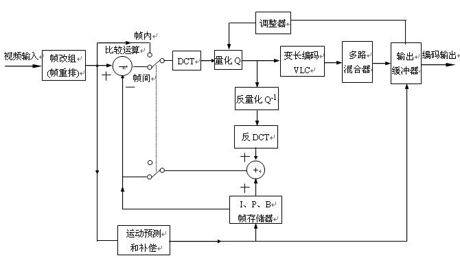
Figure 2.2.3 is a block diagram of an MPEG-1 image compression encoder. The binary digitized signal representing the luminance Y and chrominance components CB, CR first enters a frame reorganizer (or frame rearrangement circuit) to divide the picture into slices, macroblocks, and blocks. The block passes through the comparison operation circuit and then enters the DCT circuit, the quantizer, and the VLC circuit to obtain the compressed data. The data is then sent to the multiplexer and the transmission buffer. The transmission buffer is used to temporarily store the compressed data, and output the data in time series according to the control command. The buffer is coupled to the quantizer by a regulator (also known as a quantization adaptor). The adjuster can be used to detect the data temporary storage level of the buffer buffer and automatically adjust the quantization step size according to the amount of temporary data. A feedback path is provided in the encoder, which mainly includes an inverse quantizer (Q-1), an inverse discrete cosine transform (IDCT), an adder, and an IPB picture frame memory. The feedback loop is used to predict image generation, perform picture classification processing (calculate, distinguish and process IPB pictures), and is mainly used for inter-frame data compression coding processing. Also, motion prediction and compensation circuits can be used for motion compensation.
2. Image decompression circuit block diagram Image decompression circuit is referred to as decompression circuit and decoding circuit . In the VCD video disc player, after being processed by the digital signal demodulation circuit (CD-DSP), the compressed encoded video data stream is output, and the video decompression circuit is required to decompress the data and restore the uncompressed video signal. The decoding process is the inverse of the encoding. Figure 2.2.4 is a block diagram of the MPEG-1 video decompression circuit. The circuit structure is slightly simpler than the encoder. 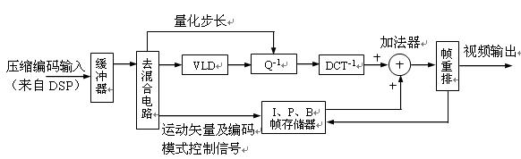
Figure 2.2.4 Block diagram of MPEG-1 video decompression circuit
The compression coded signal from the CD-DSP circuit is sent to the input buffer, and then enters the de-mixing circuit to separate the coding mode flag, motion vector (displacement vector) and image data of the image, and send them to the frame memory and decompress the main channel circuit respectively. .
The main channel needs to process the I, P, and B frame data. The data has been indicated by the data packet header according to the image coding series. These data are temporarily stored in the storage area of ​​the buffer memory, and the capacity is different according to the amount of data. In the memory area. Under the control of the microprocessor, the I picture data is first taken out in order, and sent to the VLC (variable length code demodulator), and the code bits compressed at the time of encoding are restored one by one according to the variable length code comparison table stored in the ROM. The DCT quantized value before compression, and then the quantized value of each block is divided into 64 data and multiplied by the inverse quantization parameter. These parameters are located in the relative position of the 64-bit visual mental mode quantization table stored in the ROM, and are restored to the DCT frequency. Coefficient, complete the inverse quantization process.
The inverse quantized data is sent to an IDCT (Discrete Cosine Inverse Transform) circuit. This is another inverse transform. It is also inversely transformed by the look-up table method to inversely transform the amplitude of each frequency cosine component represented by the inverse quantized value into the image (Y, CB, CR) samples before the DCT transform. Obtain the block information representative of the image before compression. The information of the four blocks constitutes a macro block, and several macro blocks constitute a slice, and then several pieces constitute the total data of the complete picture, which is an I frame picture. These heavy additions need to be done in the adder.
The recovered I frame picture data is stored in the frame memory. The I picture is added to the P picture data that is subsequently input, and the P picture can be restored, and the P picture is also stored in the frame memory. Then, according to the motion vector and the post-motion image difference (ie, B-picture data), the I and P picture storage data are added in the adder, and are controlled by the coding mode signal to determine the components of the I and P images, thereby Restore the B frame pictures before and after. The various picture data of I, P, and B obtained through the above processing need to be stored in the buffer memory, and according to the indication of the coding mode and the frame rate requirement of the output system, according to I, B, B, P, B, B, P, The normal sequence of B, B...B, I, B, B, P, B... is rearranged and output from the frame rearrangement circuit at a certain speed. The output decompressed data is sent to the D/A converter and converted into three primary color analog signals of R, G, and B.
Usually, a video encoder and a modulator are additionally provided in the decompression circuit. The video encoder can encode the three primary color signals into NTSC/PAL color television signals, and add synchronization, blanking, color burst and color subcarrier signals to output in the form of video analog full TV signals. This form of output signal needs to be delivered to the AV input port of the television receiver. However, some old-fashioned TV sets do not have an AV input port. In order to adapt to this phenomenon, the output video full TV signal needs to be modulated again at a high frequency, and the modulator outputs the TV signal in the form of RF amplitude modulation of a specific channel. At this point, the VCD machine needs to set the RF output port, and its output signal can be sent directly to the antenna input port of the TV.
Smd Resistor,Smd Chip Resistor,Thick Film Chip Resistor,Smd Resistors 10K
JINGGANGSHAN MEICHENG ELECTRONIC TRADING CO.,LTD , http://www.meicheng-tra.com