introduction
One of the key technologies for the practical application of multimedia technology is to solve the contradiction between the large amount of data after digitalization of video and audio, and the small capacity of digital storage media and communication networks. The solution is compression.
In order to support low bit rate video transmission services, MPEG (Moving Picture Experts Group) has launched the MPEG 4 standard. MPEG 4, which became an international standard in 1999, is a video and audio solution suitable for low transmission rates. It focuses more on the interactivity and flexibility of multimedia systems. The MPEG 4 video compression standard provides a highly flexible encoding method based on "content". The decoding end can "decode on demand" and add objects and information. This flexibility allows MPEG 4 to have efficient coding efficiency, content-based scalability, and robustness in vulnerable environments. These characteristics of MPEG 4 make it very suitable for handheld terminal devices with limited storage capacity. However, inverse quantization (Inverse QuanTIzaTIon, IQ), inverse discrete cosine transform (IDCT), motion compensation (MoTIon ComposiTIon, MC) and other technologies involved in MPEG 4 video decoding are typical computationally intensive transforms. For handheld terminal devices with limited processing power and limited power consumption, the real-time nature of video decoding is a great challenge.
This system uses NiosII's user-defined instructions to implement the logic calculation of IQ, IDCT, MC and other complex and highly time-consuming function modules in MPEG4 decoding on the SOPC platform composed of Nios II and FPGA, which greatly improves the decoding speed . Therefore, based on the XviD Codec released under the GPL agreement, under the Simple Profile visual framework, L1 level, QCIF (177 × 144 resolution), 25 fps MPEG 4 real-time decoding, and displayed on the LCD through DMA.
System function description
The system can be divided into four parts from the function of video file access, video decoder, YUV2RGB converter and LCD control module.
Video file access To play video files, you first need to store and read the video files conveniently. The MP4 files played by the system are compressed by XviD Codec on the PC with 4: 2: 0 YUV files. The MP4 file uses the QCIF format with a resolution of 177 × 144, 25 frames / s. In download mode, MP4 files can be written to the flash memory through the J TAG interface. In the playback mode, the Nios II processor reads the MP4 file from the Flash memory and sends it to the file buffer pool to wait for the decoder to read and decode it.
Video decoder Video decoder is the core of the system. As shown in Figure 1, the video decoder consists of five modules: entropy decoder, inverse quantization, inverse discrete cosine transform, motion compensation module and video frame buffer.

When decoding, first entropy decode the input code stream, and then determine the frame type according to the frame header information. For each macroblock, after entropy decoding, it first passes through IQ, and then undergoes IDCT transformation to obtain the spatial domain value. For the reference frame (RFrame), because there is no need for motion compensation, the transformed result is output directly, and it is also stored in the video frame buffer, which is left to the subsequent prediction frame (PFrame) for motion compensation. For the predicted frame, the motion vector is obtained by entropy decoding, and then the corresponding reference frame is searched according to the motion vector, and then the IDCT transformed prediction difference value is added to it to synthesize the final predicted frame image. The decoded predicted frames are also output all the way and stored all the way in the video frame buffer.
If the video decoding is implemented by pure software, the amount of calculation is too large to meet the real-time requirements. Using NiosII's custom instructions, the three main computationally intensive decoding units IQ, IDCT and MC are implemented in hardware logic, and the complexity of the hardware logic is exchanged for real-time decoding.
YUV2RGB converter The YUV format image decoded by the decoder is not suitable for direct LCD display. To display the decoded image on the LCD, the YUV format image must be converted to the RGB format, and the conversion relationship between the two is as follows:
R = 1. 164 (Y-16) +1. 569 (V-128)
G = 1. 164 (Y-16) +0. 813 (V-128) +0. 391 (U-128)
B = 1. 164 (Y-16) +2. 018 (U-128)
The conversion of YUV to RGB format is a very CPU-intensive process. This system uses hardware logic to realize the conversion by means of table lookup.
LCD control module The standard VGA LCD display module (640 × 480, @ 60 Hz) is a progressive scanning device. This scanning is sequential, and the next scanning point can be predicted, so that the pixel information that needs to be sent can be lined up as a data stream (St reaming). With the help of NiosII's Avalon flow mode peripheral design method, an Avalon flow mode LCD controller can be realized. A DMA controller is used to establish a DMA transfer channel between the LCD controller in streaming mode and the system SDRAM, and the pixel information is read and sent by the hardware. NiosII only needs to operate the corresponding area in SDRAM to complete the display image update.
System design structure
System hardware structure The system hardware structure is shown in Figure 2.
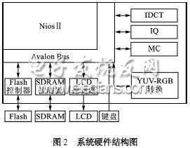
In order to achieve the real-time decoding speed of 25 fps, the four parts of the computationally intensive functional units of IDCT, IQ, MC and YUVRGB conversion are all implemented in the form of user-defined instructions.
OBD Connector
OBD Connector
ATKCONN ELECTRONICS CO., LTD , https://www.atkconn.com