High-speed CAN network data analysis technology for four-wheel independent driving electric vehicle
With the development of electric vehicles, CAN bus communication technology is more and more widely used. It can be four-wheel independent drive control on pure electric vehicles, and active safety systems such as brake anti-lock braking system (ABS) and electronic stability device (ESP). The realization of the convenience.
When designing a CAN bus communication system, it is always faced with the problem of diagnosis and analysis of CAN data. If this problem cannot be solved, the design cannot be completed. Based on the USB_CAN tool of Kvaser Leaf Professional HS, this paper develops a data analysis system on a PC by means of Visual Basic environment, and realizes CAN communication between the analysis system and the four-wheel independent drive electric motor control board. By performing diagnostic analysis on the CAN bus data, the design of the CAN bus system can be better accomplished.
Four-wheel independent drive electric vehicle control strategy
The distributed four-wheel electronic differential system used in the physical model of electric vehicles consists of a central controller, four electric wheel controllers and a CAN bus network. The layout of the electric vehicle physical model is shown in Figure 1. . 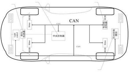
Figure 1 Layout of the distributed four-wheel electronic differential system on the vehicle body
In the distributed system, the electronic differential algorithm based on four-wheel independent control is divided into two parts: the vehicle differential algorithm and the speed control algorithm, wherein the speed control algorithm is for each electric wheel speed. The central controller and the four electric wheel controllers are connected to form a real-time control network via the CAN bus.
During the control of the system, the central controller obtains the steering angle signal of the vehicle from the steering sensor and the vehicle speed setting signal from the handle handle through A/D sampling, and obtains four current wheels respectively through the vehicle differential algorithm. The required speed, and this result is used as the current speed control set value corresponding to the wheel, and sent to the corresponding electric wheel controller through the CAN bus. The four wheel controllers use the speed setting value received from the CAN bus as the control target, and use the electric speed control algorithm to control the respective electric wheels, so that the actual speed of each electric wheel can meet the requirements of the vehicle differential algorithm in real time. Further, the smooth steering of the electric vehicle is realized.
Four-wheel independent drive electric vehicle CAN control network
Through the CAN bus, the four-wheel drive electric vehicle central controller transmits the set value of the wheel speed and the like to the controller of each wheel. At the same time, each motor controller feeds back information such as the actual speed to the central controller through the CAN bus. The topology of the CAN network is shown in Figure 2. 
Figure 2 CAN control network topology
There are five CAN nodes in the whole network: four electric wheel motor controllers a, b, c, d, and one electric vehicle central controller e.
When designing the application layer protocol, a reasonable bus arbitration priority order must be programmed for the bus message according to the actual application to improve the real-time performance of CAN communication. In this application, the downlink data, that is, the control command issued by the central controller to each of the electric wheel motor controllers, has a higher priority than the uplink data, that is, the feedback information of each electric wheel motor controller. In addition, the commands sent by the central controller to the four wheel controllers must be synchronized to provide a reliable precondition for subsequent control.
Taking into account the above factors, this paper designs the CAN data message ID system as shown in Table 1.
The motor controllers a, b, c, and d control the left front wheel, the right front wheel, the left rear wheel, and the right rear wheel of the electric vehicle, respectively. The structure of the CAN message data field sent by the central controller is shown in Figure 3. 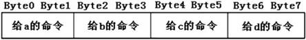
Figure 3 Central controller CAN message data domain structure
The CAN data sent by the central controller with IDs 0x010 and 0x020 indicates the set value of the speed and torque. The corresponding actual value is the analog quantity. Here, the 16-bit length finite precision fixed point number is used. The upper 9 bits of the 16-bit data represent integers, and the lower 7 bits represent decimals, that is, fixed-point numbers in the 9Q7 format. For the CAN data sent by the central controller with the ID 0x00F, the command sent to each motor controller is also 16-bit data, the lower 8 bits represent the brake command, and the upper 8 bits represent the control mode selection command.
The structure of the CAN message data field in which the four motor controllers feed back the current status information to the central controller is as shown in FIG. 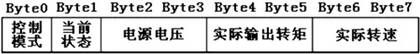
Figure 4 Motor control feedback status information structure
There are two ways to trigger CAN bus messages: event triggering and time triggering. The former applies to the discrete state of the switching state of the transmission time, such as the brake command and control mode selection command; the latter is applicable to the analog quantity that continuously changes in the transmission time, such as the speed setting value and the torque setting value. Since the two types of bus information are combined in the control system, the event triggering and the time triggering are combined to transmit.
Introduction to Kvaser Leaf Professional HS
Kvaser Leaf Professional is a single-channel USB interface for CAN and LIN. It provides the possibility to easily connect several interfaces to a PC, making it easy to connect multiple Kvaser Leaf devices on the same USB Hub without additional Connection. In addition, it has excellent EMC (Electro MagneTIc CompaTIbility) performance and plug and play characteristics. At the same time, since multiple devices can be connected to one USB Hub, each device can be powered by the Hub and has low power consumption.
The library functions provided by Kvaser are very rich, users can call the corresponding library functions according to their own needs, and flexibly process CAN bus data.
Game Machine Harness advantages:
1).which is a full jamma harness with connectors for power supply, monitor, joysticks and buttons(microswitches).
2).It comes with edge connector, push button lugs, power lead, RGB monitor cable. Also includes extra button loom and connectors for all parts of your jamma.
3).We can make custom harnesses as customer request.
Game Machine Harness
Game Harness,Blue Arcade Game Machine,Game Machine Wire Harness,Game Machine Harness
Dongguan YAC Electric Co,. LTD. , http://www.yacenter-cn.com