The dual channel audio amplifier volume controller generally uses a coaxial dual potentiometer. Due to the poor consistency of the ordinary dual carbon film potentiometer, the balance of the two channels cannot be guaranteed, especially in the small signal area. serious. In addition, this potentiometer has poor wear resistance and short life. In actual use, it was found that the first problem with the power amplifier was that the volume control potentiometer was damaged. Volume control potentiometer to solve the above-described disadvantages of the method:
(1) Switch to a high-end double-connected potentiometer, but the problems of consistency and wear still exist;
(2) The multi-level analog switch of the integrated circuit is used to switch the resistor string, but the channel will bring distortion and noise when the signal is small;
(3) Use multi-band switch to complete the switching of the resistor string. However, it can only be operated manually, and it feels bad when turning, and its contacts are generally not sealed, which is easy to be dirty and oxidized;
(4) Step-by-step switching using micro electromagnetic relay. This is a more practical method, and its production cost is lower than high-end potentiometers.
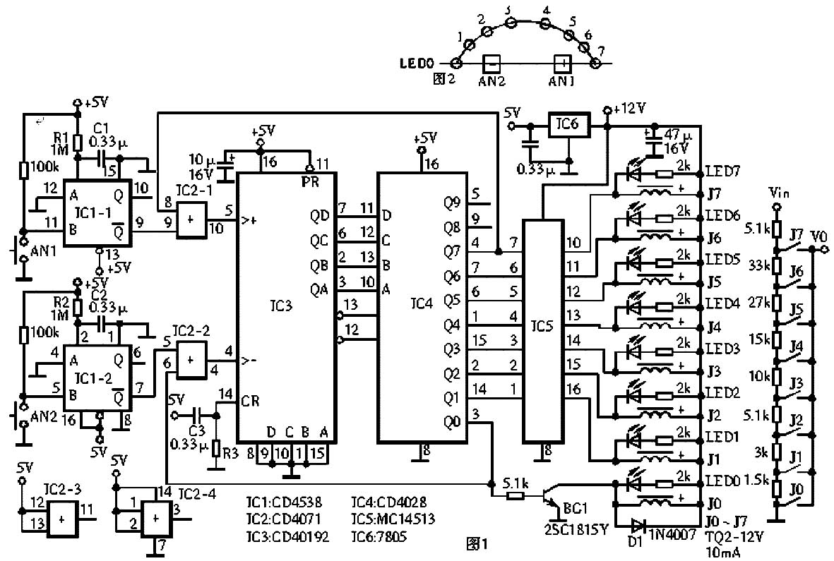
The circuit principle is shown in Figure 1. This circuit uses a CMOS digital circuit. In the figure, AN1 is the volume "plus" button, and AN2 is the volume "minus" button (both buttons use micro switches). To eliminate jitter generated when the switch is pressed, added debounce circuit constituted by IC1 and the like. The output pulse width is determined by the RC timing circuit, which is about 0.3s according to the figure.
The IC3 counter uses dual clock operation, that is, when the counting pulse is sent from the pin, the counter performs up counting, and if the pulse is sent from the pin, the counter performs down counting. The counter requires that the count pulse is a negative pulse. The first pin is the clearing end. In order to ensure that the counter is at the zero position (equivalent to the minimum volume) after power-on, R3 and C3 will automatically clear after booting. Counter BCD code data output by the QD ~ QA, respectively, corresponding to the size of the volume, small to large can be divided into 10 levels. After IC3 is output, it is sent to IC4 for decoding, which can be translated into Q0 ~ Q9 10-channel signals (0000 corresponds to Q0, 1001 corresponds to Q9, and so on), which can control the switching of 10 relays. When this reversible counter is at the minimum value of 0000, if a pulse is input from the countdown terminal, the counter will become the maximum value of 1001. Similarly, when it is at the maximum value of 1001, if a pulse is input from the count-up terminal, the counter will become the minimum value of 0000. To solve this problem, the OR gate IC2-1 can be added to the Q7 terminal of IC4. When Q7 is "1", the volume is at this time, the IC2-1 gate is blocked, and the count-up pulse generated by AN1 cannot reach IC3. Similarly, the down counting terminal of IC3 is blocked by the control gate IC2-2, and the down counting signal generated by AN2 is invalid at this time. From a practical point of view, 8-level volume control is enough.
IC5 is used to drive the relay (7 channels), and BG1 is used to drive the remaining one. The LED is used to indicate the position of the volume control. The eight normally open contacts of the relays J0 ~ J7 are connected to the series resistance chain, and the total resistance of the chain is 100kΩ. The small relay selected here is a double-contact structure, which can control the left and right channels at the same time (only one channel is shown in the figure).
High-quality products should be selected for relays and attenuation resistors. The relay uses the ultra-small sealed type (blue-black plastic shell) TQ2-12V, and can also be replaced by EA2-12V (red plastic shell). The resistance of the resistors in the chain available 1 / 4W or 1 / 2W, error of ± 1% metal film resistors high. Two buttons and eight LEDs are arranged on the panel as shown in Figure 2. The relay drive circuit uses a single 12V power supply. After the circuit is assembled, as long as the element and the wiring is correct, debugging can work properly. The circuit in Figure 1 is divided into 8 levels of control. If you want to control more finely, you can change IC3 to CD40193, IC4 to CD4514, and then use three MC14513 to drive 16 small relays, you can become 16 files. In addition, if the switch signals controlled by the remote control circuit are connected in parallel at AN1 and AN2, the infrared remote control volume control function can be realized.
Abstracts by Zhang Lijun and others from "Electroacoustic Technology"

Follow WeChat

Download Audiophile APP

Follow the audiophile class
related suggestion
& N ...
![[Photo] Practical LM2575 series of switching power supply circuit](http://i.bosscdn.com/blog/20/06/41/7211925766.jpg)
â—† Overview of circuits Many homes now have televisions
![[Photo] Practical home TV station transmission circuit](http://i.bosscdn.com/blog/20/06/41/719132274.jpg)
General touch volume controller circuit ...
The question suggests that nickel-cadmium or nickel-metal hydride batteries have strict requirements for charging. But the big ones sold on the market ...
![[Photo] Practical constant current charger](http://i.bosscdn.com/blog/20/06/41/5232039823.gif)
'+ data.data.username +' '; dom + ='
Din Rail Multifunctional Power Meter
The DIN-rail mounted multifunctional power meters support electrical parameters measurement, energy measurement and power quality analysis. Some models can be equipped with many I/O modules for status monitoring and control of the field equipments. They can be easily integrated with a variety of intelligent power distribution systems and energy management systems, to share abundant monitoring data and power quality data.
Din Ralin Multifunctional Power Meter,Mid Digital Kwh Energy Meter,Electric Sub Meter With Mid,Din Rail Type Multifunction Power Meter
Jiangsu Sfere Electric Co., Ltd , https://www.elecnova-global.com