A timer is used to control the I/O port output PWM waveform, thereby driving the LED lamp to appear similar to the respiratory frequency.
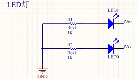
Hardware circuit diagram:
My harvest:
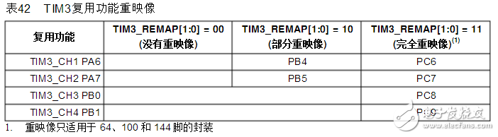
This is a description of the re-imaging of the TIM3 general-purpose timer multiplexing function in the STM32 data sheet. Assuming that PA6 is used as the PWM output, it can be seen from the figure that PA6 corresponds to channel 1 of TIM3.
The function to enable TIM3 channel 1 is
TIM_OC1Init();1
Similarly, if you want to enable PA7, which corresponds to channel 2 of TIM3, then the function that enables channel 2 is:
TIM_OC2Init()1
By analogy, it should be noted that the function of enabling different channels of different timers is slightly different, preventing the TIM_OC1Init() function from being called in the program to enable the occurrence of TIM3 channel 2.
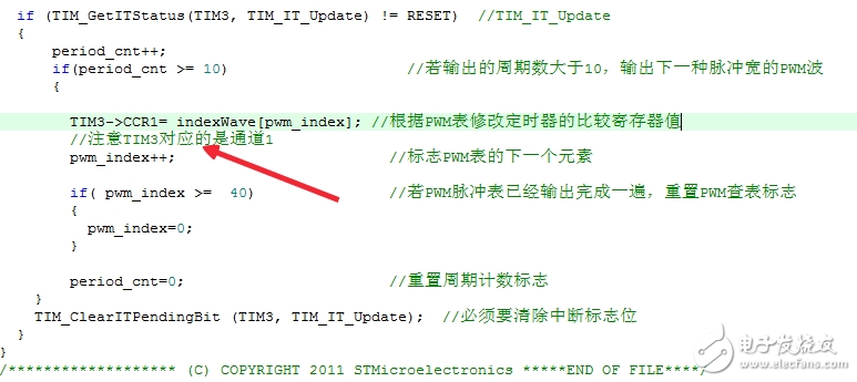
Note here, assuming that channel 1 of TIM3 is used, then it is written here.
TIM3-》CCR11
Similarly, if you use channel 2 of the TIM3 timer, you should change it accordingly.
TIM3-》CCR21
This is also to prevent the original plan to use the channel 1 of the TIM3. Instead, it is written here as a TIM-"CCR2. This kind of error is generally hidden and not easy to find.
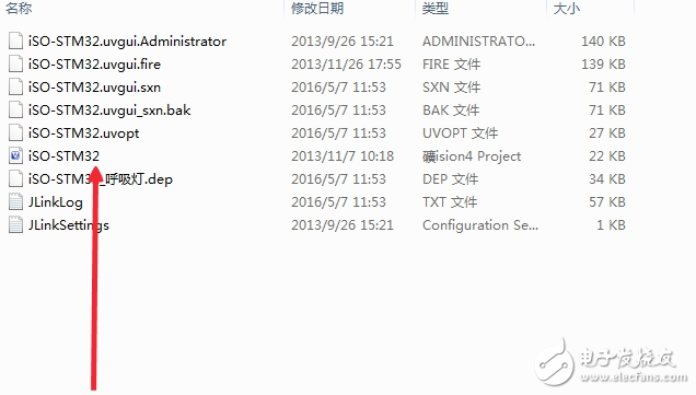
The corresponding program has been uploaded, but I don't know why I can't display the download address of the program here. I need to download it and go to my resource to download it.
Project file is
Progect–â€RVMDK(uv4)–â€iSO_STM32
/* * Description:
*PA0: KEY1; PA1: KEY2;
*PA2: LED1; PA3: LED2;
*PA9: USART1_TX; PA10: USART1_RX
*/
#include "stm32f10x.h"
#include "stm32f10x_rcc.h"
#include "stm32f10x_gpio.h"
#include "stm32f10x_tim.h"
#include "stm32f10x_pwr.h"
#include "stm32f10x_exti.h"
#include "system_stm32f10x.h"
#include "misc.h"
Void RCC_Configuration(void);
Void GPIO_Configuration(void);
Void TIM2_Configuration(void);
Void delay_ms(u16 time);
Int main()
{
U8 led_fx=1;
U16 led_dt=0;
RCC_Configuration();
GPIO_Configuration();
TIM2_Configuration();
While(1)
{
Delay_ms(10);
If(led_fx==1)
{
Led_dt++;
}else{
Led_dt--;
}
If(led_dt"100) led_fx=0;// can be the same as the initial value
If(led_dt==0) led_fx=1;
TIM_SetCompare3 (TIM2, led_dt); / / channel 3 no heavy image is PA2 corresponding to LED1
TIM_SetCompare4(TIM2, led_dt); / / channel 4 no heavy image is PA3 corresponding LED2
}
}
Void RCC_Configuration(void)
{
SystemInit();
RCC_APB2PeriphClockCmd(RCC_APB2Periph_GPIOA, ENABLE);
RCC_APB1PeriphClockCmd(RCC_APB1Periph_TIM2, ENABLE);
/ / GPIO_AFIODeInit (); and the same effect below, you can view the source code proof
RCC_APB2PeriphClockCmd(RCC_APB2Periph_AFIO, ENABLE);
}
Void GPIO_Configuration(void)
{
GPIO_InitTypeDef GPIO_InitStructure;
//GPIO_PinRemapConfig(GPIO_PartialRemap2_TIM2, ENABLE); // port mapping function
GPIO_InitStructure.GPIO_Pin = GPIO_Pin_2|GPIO_Pin_3; //GPIO_Pin_3 corresponds to channel3, the main function is changed to: TIM_SetCompare3
GPIO_InitStructure.GPIO_Speed ​​= GPIO_Speed_50MHz;
GPIO_InitStructure.GPIO_Mode = GPIO_Mode_AF_PP;
GPIO_Init(GPIOA, &GPIO_InitStructure);
}
Void TIM2_Configuration(void)
{
TIM_TimeBaseInitTypeDef TIM_TimeBaseStructure;
TIM_OCInitTypeDef TIM_OCInitStructure;
TIM_DeInit(TIM2);
TIM_InternalClockConfig(TIM2);
/ / Timer initialization
TIM_TimeBaseStructure.TIM_Period = 100-1; / / initial value is 100, 2MHz = 2000KHz, 2MHz / 100 = 0.02MHz, all cycles T = 1 / 0.02MHz = 50us, oscilloscope display period should be 50us
TIM_TimeBaseStructure.TIM_Prescaler = 36-1; // 36 times, 72MHz/36=2MHz
TIM_TimeBaseStructure.TIM_ClockDivision = 0;
TIM_TimeBaseStructure.TIM_CounterMode = TIM_CounterMode_Up;
TIM_TimeBaseStructure.TIM_RepetitionCounter = 0;
TIM_TimeBaseInit(TIM2, &TIM_TimeBaseStructure);
//PWM initialization
TIM_OCInitStructure.TIM_OCMode = TIM_OCMode_PWM1;
TIM_OCInitStructure.TIM_OutputState = TIM_OutputState_Enable;
TIM_OCInitStructure.TIM_Pulse = 50; / / duty cycle value is 50, so the duty cycle is: 50 / 100 = 50%
TIM_OCInitStructure.TIM_OCPolarity = TIM_OCPolarity_Low;
TIM_OC3Init(TIM2,&TIM_OCInitStructure);
TIM_OCInitStructure.TIM_Pulse = 20;
TIM_OC4Init(TIM2,&TIM_OCInitStructure);
//TIM_OC3PreloadConfig(TIM2, TIM_OCPreload_Enable);
//TIM_ARRPreloadConfig(TIM2, ENABLE);
TIM_Cmd(TIM2, ENABLE);
TIM_CtrlPWMOutputs(TIM2,ENABLE);
}
Void delay_ms(u16 time)
{
U16 i=0;
While(time--)
{
i=12000;
While(i--);
}
}
Anti-Jamming RC Arc Extinguisher
Anti-Jamming RC Arc Extinguisher
")
Anti-Jamming RC Arc Extinguisher
YANGZHOU POSITIONING TECH CO., LTD. , https://www.cnchipmicro.com