1 Overview
In the past decade or so, the level of automation in China's textile machinery industry has been significantly improved, and automation technology has been commonly used in new types of textile machinery. The content of this technology includes advanced information processing and control technology, that is, a computer-based core, a control system consisting of a PLC, an industrial control computer, a microcontroller, a human-machine interface, and a field bus. Advanced drive technology includes frequency conversion speed control, AC servo, stepping motor, detection sensor technology and actuators. The representative mechanical and electrical integration products of cotton textile equipment, such as the new type of roving frame, simplify the use of automation technology, improve performance, improve quality, and facilitate operation, and upgrade the grade and level of equipment. Touch screen man-machine interface, easy to operate. The frequency conversion speed regulation reduces the noise and power of the equipment and reduces the mechanical loss. With the deeper understanding of the textile technology in the industry, the function of the roving frame is more perfect, making the domestic roving frame more suitable for domestic applications than the imported roving frame. .
In recent years, the extensive application of heavy-quantity and high-efficiency technology has brought new spinning technologies to a higher level of development. This article describes the control system of a certain type of roving machine that integrates Delta Automation products such as the DVP series of PLCs and inverters. High-efficiency spinning technology not only improves the production efficiency of the equipment, but also improves the technical configuration of the control system, improves the working stability and high efficiency of the roving machine equipment, and at the same time improves the quality of the spindle products, and also reflects the high control system. The value for money, worthy of peer promotion applications.
2 Process Analysis
A certain type of roving machine uses a high-efficiency technology and rational selection of configuration technology parameters, finely analyzes and optimizes the appropriate technical parameters through experiments, and reasonably configures the roving weight, draft multiple of the roving back area, roller gauge, top roller positioning, Roving twist coefficient, jaw gap and other high-efficiency process parameters are the guarantee for improving the roving and improving the yarn quality.
Its technical characteristics are as follows:
Suitable spinning line density (tex) 200-1250
Suitable for spinning fiber length (mm) 22-65
Draft multiple (times) 4.2-12
The highest mechanical spindle speed (r.min-1) 1600
The highest process spindle speed (r.min-1) 1200
Range of twist (æ»/m) 18-80
Package size (mm) ф150×400
Pitch (mm) 220
Draft form Four rollers double short aprons
Pressurized Form TexParts PK-1500 or YJ4-190×4
Lower roller diameter (mm) Ñ„ 28.5 Ñ„ 28.5 Ñ„ 28.5 Ñ„ 28.5
Roller diameter (mm) Ñ„28 Ñ„28 Ñ„25 Ñ„28
3 control system
3.1 Control System Configuration
The technical solution configuration details are shown in Table 1:
No.
Component name
Model specifications
amount)
Note
1
HMI
DOP-A10THTD1
1
10.4â€, 65536 colors
2
PLC host
DVP32EH00M
1
Differential signal output
3
DIO expansion unit
DVP08HM11N
1
8DI
4
DIO expansion unit
DVP08HN11R
1
8DO
5
Inverter
VFD075V43A-2
1
7.5KW, open loop
6
Inverter
VFD022V43A-2
1
2.2KW, closed loop
7
Inverter
VFD015V43A-2
1
1.5KW, closed loop
8
PG feedback card
EMV-PG01L
2
Speed ​​closed loop feedback
Table 1 Technical solution configuration table
The above table only lists the main components of the control system, in addition to low-voltage electrical appliances (low-voltage circuit breakers, electromagnetic contactors, electromagnetic relays, energy storage DC capacitors, buttons, lights, etc.), detection sensors (proximity switches, limit switches, etc.) This will not be repeated here.
3.2 Control System Principle and Block Diagram
The upper computer of the control system adopts Delta 10.4 inch 65536 color true color touch screen. The man-machine interface communicates in real time through RS232C mode and the lower position controller PLC via COM1 communication port, realizes roving machine equipment operation parameter information display, operation parameter instruction input, equipment alarm Information display and other functions; the lower controller PLC executes the user logic ladder program, according to the equipment technology conditions, the input point digital signal acquisition, program execution, refresh the output point status, perform the corresponding output action, through the PLC's own integrated COM2 The communication port sends the frequency command to the first 7.5KW inverter in RS485 mode. The PLC high-speed pulse input interface simultaneously receives the 7.5KW inverter to drive the encoder pulse signal of the main motor shaft end, and collects the high-speed pulse signal PLC program for operation and processing; The 7.5KW main motor shaft encoder pulse output signal drives the second 2.2KW winding inverter at the same time. The 2.2KW winding inverter integrated speed closed loop PG card forms the closed loop speed control system. The PG feedback card receives the 7.5KW main motor. The pulse input of the encoder is used as the frequency command source, and the PG card frequency output is itself programmed. High-speed pulse signal to the third 1.5KW inverter; 1.5KW inverter integrated speed closed-loop PG card, which constitutes the speed closed-loop control system, PG feedback card to receive 2.2KW winding motor encoder pulse input frequency instruction source.
It is worth mentioning that the encoder signal output type is selected as the differential line driver (Line Driver). Delta DVP32EH00M model PLC can directly receive line drive differential form of high-speed pulse signal, and PG speed closed-loop feedback card also selects receive differential form. The pulse signal, using the line drive differential form of high-speed pulse signal, effectively overcomes the phenomenon of high-speed pulse signal loss or distortion caused by various types of noise interference in the industrial field. Control system block diagram shown in Figure 1:
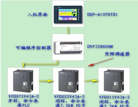
Figure 1 Block diagram of the control system
3.4 The use of frequency conversion PLC technology
This type of high-speed suspension type roving frame adopts PLC as master controller, three-axis linkage variable frequency drive technology, and three-motor linkage transmission are respectively transmitted by two H-shaped timing belts. Its unique transmission technology features make this machine through frequency conversion. Different spindle speeds and roller speeds are achieved at speed to complete the drafting and twisting process; the control of the speed of the bobbin drafts and the constant speed of the spindle and the associated fractional speed combine to achieve the forming and winding tasks.
3.5 The use of patented free reversing technology
This type of roving machine took the initiative of 100 companies to open up the free-reversing PLC control program, so that the steering of the lifting frequency conversion motor can realize the free commutation of the spinning process, and the commutation time of one hundred milliseconds has reached the technical requirements of fast and free commutation. .
3.6 Application of D-type Drafting
This type of roving machine adopts a D-type drafting pattern with four rollers and double short aprons. Based on the drafting pattern of the three-roller double short aprons, a pair of converging rollers is added in front: namely, the front roller and the second roller. A consolidation zone was formed between the two zones, and a collector was added to the zone so that the second and third rollers became the main draft zone. The third and fourth rollers became the secondary draft zone in the rear zone, so the drafting and clustering were completed. The purpose of the application is to separate, that is, the draft is not bundled and the bundle is not drafted, thereby reducing the pressure peak on the drafting roller area to a certain extent, improving the working conditions of the roller drafting, the setting of the bundle finishing area and the fiber floating The changes in the area have increased the fluctuating characteristics of the fiber speed change point, which greatly improves the quality of the roving sliver compared to the three-roller double-short apron drafting type.
3.7 Unexpected Power Shutdown and Shutdown
As the roving machine uses the on-site power supply, unexpected power failure may occur. If the equipment does not have backup power, when the equipment is shut down unexpectedly, the momentary power failure of the PLC, HMI and inverter will cause the drive motor of the equipment to run in freewheeling mode. At this time, the control system cannot remember The current operating position information and operating parameter information, the re-start the system will appear chaotic parameters, so the roving machine system is bound to install the power storage device, in order to prepare the power in case of unexpected power off, ensure PLC, HMI and inverter The power supply is stable before the equipment stops normally. Taking into account the economic costs, the use of large DC capacitors as energy storage components than the choice of high-power UPS to save costs, and the UPS response time is longer than the capacitor, comprehensive consideration of the use of large-capacity DC capacitors as energy storage components, the practice has proved to fully meet the technology Requirements, after a power outage, the release of power through a large-capacity capacitor to supply PLC and inverter, PLC can continue to run 60S, the inverter can also continue to run 50S, these times are enough to effectively deal with the normal shutdown process after unexpected power failure. It should be noted that for DC power supply to Delta PLC, the positive terminal of DC power supply is connected to the N terminal, and the negative terminal of DC power supply is connected to the L terminal. For the three inverters, the common DC bus DC-BUS is required, that is, three inverters. The busbars are connected in parallel and uniformly connected to the bulk storage capacitor assembly.
4 After the inverter debugging parameters:
(1) The main motor 7.5KW inverter parameter adjustment is shown in Table 2:
00-10
Control Method
2
00-20
Source of Freq.
1
00-21
Source of Oper.
1
01-00
Max Output Freq.
Hz
50
01-01
Motor1 Fbase
Hz
50
01-02
Max Out-Volt 1
V
380
01-12
1st Accel Time
Sec
12
01-13
1st Decel Time
Sec
7
02-04
Multi-Fun Input4
8
05-01
Motor1 Rated A
Amps
16.6
05-02
Motro1 Rated P
Kw
7.5
05-03
Motor1 Rated
RPM
1440
05-04
Motor1 Poles
4
05-05
Motor1 No-Load
Amps
3.77
05-06
Motor1 Rs
Ohm
1.43
05-07
Motor1 Rr
Ohm
0.798
05-08
Motor1 Lm
mH
344.5
05-09
Motor1 Lx
mH
24.5
09-00
VFD Comm Address
1
09-01
COM1 Baud Rate
Bps
9.6
09-02
COM1 Fault Treat
0
09-03
COM1 Time Out
Sec
0
09-04
COM1 Protocol
2
11-00
System Control
2
(2) Winding motor 2.2KW inverter parameter adjustment is shown in Table 3:
00-10
Control Method
3
00-20
Source of Freq.
4
00-21
Source of Oper.
1
01-00
Max Output Freq.
Hz
50
01-01
Motor1 Fbase
Hz
50
01-02
Max Out-Volt 1
V
380
01-12
1st Accel Time
Sec
0.01
01-13
1st Decel Time
Sec
0.01
01-20
JOG Accel Time
Sec
0.01
01-21
JOG Decel Time
Sec
0.01
01-22
JOG Frequency
Hz
36
05-01
Motor1 Rated A
Amps
5
05-02
Motro1 Rated P
Kw
2.2
05-03
Motor1 Rated
RPM
1440
05-04
Motor1 Poles
4
05-05
Motor1 No-Load
Amps
2.42
05-06
Motor1 Rs
Ohm
6.191
05-07
Motor1 Rr
Ohm
4.076
05-08
Motor1 Lm
mH
510.2
05-09
Motor1 Lx
mH
61.7
10-00
Encoder pulses
1024
10-01
PG input setting
2
10-15
PG Ref Input
1
10-16
PG Scale Factor
4
10-17
PG Elect. Gear A
1,000
10-18
PG Elect. Gear B
1284
11-00
System Control
1
11-01
System Jm
PU
658
Table 3 Parameters of 2.2KW Inverter for Winding Motor
(3) Lifting motor 1.5KW Inverter adjustment parameters are shown in Table 4:
00-10
Control Method
3
00-20
Source of Freq.
5
00-21
Source of Oper.
1
01-00
Max Output Freq.
Hz
50
01-01
Motor1 Fbase
Hz
50
01-02
Max Out-Volt 1
V
380
01-12
1st Accel Time
Sec
0.01
01-13
1st Decel Time
Sec
0.01
01-20
JOG Accel Time
Sec
0.01
01-21
JOG Decel Time
Sec
0.01
01-22
JOG Frequency
Hz
30
02-03
Multi-Fun Input3
5
02-04
Multi-Fun Input4
twenty four
02-05
Multi-Fun Input5
25
05-01
Motor1 Rated A
Amps
1.68
05-02
Motro1 Rated P
Kw
0.37
05-03
Motor1 Rated
RPM
1440
05-04
Motor1 Poles
4
05-05
Motor1 No-Load
Amps
0.87
05-06
Motor1 Rs
Ohm
42.534
05-07
Motor1 Rr
Ohm
25.501
05-08
Motor1 Lm
mH
1323.7
05-09
Motor1 Lx
mH
280.2
10-00
Encoder pulses
256
10-01
PG input setting
2
10-15
PG Ref Input
3
10-16
PG Scale Factor
2
10-17
PG Elect. Gear A
1,000
10-18
PG Elect. Gear B
1517
Table 4 Adjusting parameters of lifting motor 1.5KW inverter
5 Conclusion
To provide customers with a good cost-effective perfect integration program is the marketing strategy of Delta Electronics, providing a stable and reliable system integration solution is to ensure customer service, this roving machine automation control system integration and application of Delta HMI, PLC, inverter, etc. Automation products have developed a stable and reliable system for customers, not only meeting the technical requirements of customers' textile machinery equipment, but also improving the quality of spinning products and the working efficiency of the equipment. It has been greatly recognized by customers and users, and the customer said After the successful technical transformation of the roving machine, the plant has been successfully tested, and the mature technology plan will be used in the follow-up to mass production equipment. This proves once again that Delta Electric is a reliable partner for customers.
San Shi Tian extracted from the network
ã€references】
[1] DVP-PLC Application Technical Manual Procedures, Delta Internal Data, 2007
[2] Delta DVP-PLC application technology manual special module, Delta internal data, 2007
[3] Delta DOP series human-machine interface application technical manual, Delta internal data, 2007
[4] Delta VFD-VE Series AC Variable Frequency Drive User Manual, Delta Internal Data, 2007
[5] Selection and Application of Frequency Converters in Industry Liu Jideng and other scientific and technological information No. 23, 2009